This lesson uses D/A conversion to make the LED lights on the Propeller Activity Board (original or WX version) brighter or dimmer.
In the lesson Blink a Light, the Propeller is programmed to output 3.3 V on an I/O pin to turn a light on, and to output 0 V to turn a light off. The Propeller can also be programmed to switch an I/O pin between 0 and 3.3 V very rapidly, in a pattern that delivers an average output voltage anywhere between 0 V and 3.3 V. These duty-modulation patterns, called duty-modulation signals, change the average “on” time for the LEDs which our eyes will interpret as different levels of brightness.
Circuit
This activity is not compatible with the Propeller FLiP.
Although you can do this kind of duty-modulation D/A conversion for LEDs on any Propeller I/O pin, P26 and P27 have LEDs built into the Propeller Activity Board (original or WX version), so let’s use those.
On the Propeller Activity Board (original or WX version), P26 and P27 are also connected to filter and amplifier circuitry that converts the duty-modulated D/A signals into steady voltages. Those voltages are then available at the D/A sockets, D/A0 and D/A1. These sockets are useful for other circuits that might need need a specific steady voltage but draw a varying amount of current. We can use the board’s A/D converter to measure the voltages we set on the D/A sockets.
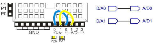
- Connect D/A0 to A/D0 and D/A1 to A/D1.
Note: This lesson is designed for the Propeller Activity Board (original or WX version). On the Propeller Board of Education, you can use this D/A technique to control the brightness of LEDs. However, the Propeller Board of Education uses a different A/D converter chip, so trying to use the A/D sockets to measure the voltage at the D/A sockets will not work.
Test Code
This example program will make P26 send a 2.5 V signal to D/A0, and P27 send a 1 V signal to D/A1. As a result, the P26 LED should be considerably brighter than P27.
- Click SimpleIDE’s Open Project button.
- Open Set and Measure Volts from…Documents\SimpleIDE\Learn\Examples\Circuits.
- Click the Run with Terminal button.
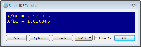
- Verify that the P26 LED is brighter than the P27 LED, and also check the SimpleIDE terminal and make sure it displays measurements of about 2.5 V for A/D0 and 1 V for A/D1.
How it Works
The dac_ctr(26, 0, 194) call has three parameters: pin, channel, and dacVal. Pin is the Propeller I/O pin that you want to send the D/A signal, and this example uses 26.
The channel parameter allows you to select one of two counter modules (0 or 1) in a Propeller core (also called a cog) to generate the duty-modulation signal. This example uses channel 0.
The dacVal parameter allows you to set the voltage as the number of 256ths of 3.3 V. This example uses 194, so we’ll expect D/A1 to send 194/256ths of 3.3 V. That’s 2.5 V because 194/256 * 3.3 V ≈ 2.5 V.
Next, the dac_ctr(27, 1, 78) call sends a D/A signal with P27, channel 1, and D/A1 gets 78/256ths of 3.3 V ≈ 1 V.
Since we added wires to connect the D/A voltage outputs to the A/D voltage inputs, we need code to read and display the those voltages. A call to adc_volts(0) returns the measured D/A0 output, and adc_volts(1) returns D/A1’s output. Instead of storing those measurements in variables, the calls to adc_volts are nested right in the print statements, which can use their return values directly. So, print(“A/D0 = %f\n”, adc_volts(0)) sends the result of the adc_volts(0) call straight to the SimpleIDE Terminal. Likewise with print(“A/D1 = %f\n”, adc_volts(1)).
/*
  Set and Measure Volts.c

  Set D/A0 to 2.5 V and D/A1 to 1 V, and measure with A/D0 and A/D1.
*/

#include "simpletools.h"                         // Include simpletools
#include "adcDCpropab.h"                         // Include adcDCpropab

int main()                                       // main function
{
  adc_init(21, 20, 19, 18);                      // CS=21, SCL=20, DO=19, DI=18

  dac_ctr(26, 0, 194);                           // D/A ch 0 -> 2.5 V to D/A 0
  dac_ctr(27, 1, 78);                            // D/A ch 1 -> 1 V to D/A 1

  print("A/D0 = %f\n", adc_volts(0));            // Display A/D0 volts
  print("A/D1 = %f\n", adc_volts(1));            // Display A/D1 volts
}
The channel 0 and channel 1 parameters don’t have anything to do with D/A0 and D/A1. D/A0 makes a steady voltage from P26 signals and D/A1 makes a steady voltage from P27 signals, no matter which channel you use.
The great thing about channels is that you can use them to move a D/A signal off one pin and onto another. For example, adding dac_ctr(9, 0, 194) after the rest of the statements would turn the P26 light off, and then turn a P9 light on (if you had an LED connected to P9, of course).
Did You Know?
- dac_ctr function – This function from the simpletools library offers two 8-bit channels and uses another Propeller core to process the signaling.
- 8-Bit – An D/A converter with 256 voltage levels (from 0 to 255) is called 8-bit because it takes 8 binary digits to count from 0 to 255. A 7-bit converter would count offer values from 0 to 127. More generally, if you have an n-bit converter, it splits the voltage up into 2n levels, from 0 to 2n-1. For example, try 28 in your calculator, it’ll give you 256.
- LSB – Each voltage increment is called an LSB (short for Least Significant Bit). With a 3.3 V, 8-bit D/A converter, the LSB is 3.3 V/256 = 0.012890625. If the D/A converter is sending a value of 78, that’s actually 78 LSBs, or 78 * 0.012890625 ≈ 1 V.
- One pin at a time, please – With dac_ctr, if you make channel 0 do D/A on another I/O pin, it will stop doing D/A on the pin it was working on. For example, you could call dac_ctr(26, 0, 150) and then pause for 2 seconds, and then call dac_ctr(27, 0, 150). The P26 light would turn off, and the P27 light would turn on at the same brightness.
- libdactr library – If you need more than 2 channels of D/A, there’s a libdactr library in ..Documents\SimpleIDE\Learn\Simple Libraries\Convert folder that gives you more flexibility.
Try This
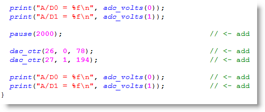
Let’s try making the voltages hold at D/A0 = 2.5 V and D/A1 = 1 V for 2 seconds, then change to D/A0 = 1 V and D/A1 = 2.5 V.
- Use the Save Project As button to save a “try this” copy of your project in …Documents\SimpleIDE\My Projects.
- Modify the main function as shown below.
- Run the program and verify that the P26 LED is brighter than the P27 LED for 2 seconds, and then they swap so that P27 is brighter.
Your Turn
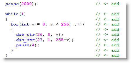
You can use variables and loops to gradually change the voltages, for a fade-out effect.
- Use the Save Project As button to save a “your turn” copy of your project in …Documents\SimpleIDE\My Projects.
- Add this code between the last print statement and the last curly brace }.
- Since we aren’t displaying more voltages here, you can just use the Load RAM & Run button. Keep an eye on the lights, they should alternately fade from full brightness.