Ping)))Dar Display with ActivityBot and BlocklyProp

In this activity, you will build the PING))) sensor circuit and use it to measure distances of a variety of objects to get familiar with what it does and does not detect. The PING))) sensor just needs power, ground, and one signal connection for the Propeller to get distance measurements.
In this activity, we will measure the distance to a variety of objects to get familiar with what the PING))) does, and does not, detect. The PING))) sensor needs power, ground, and one signal connection for the Propeller to get distance measurements.
In this activity, we will measure the distance to a variety of objects to get familiar with what the PING))) does, and does not, detect. The PING))) sensor needs power, ground, and one signal connection for the Propeller to get distance measurements.
In this activity, you will build the PING))) sensor circuit and use it to measure distances of a variety of objects to get familiar with what it does and does not detect. The PING))) sensor just needs power, ground, and one signal connection for the Propeller to get distance measurements.
Contact sales@parallax.com if parts or components are missing.
The Arlo Complete Robot System includes:
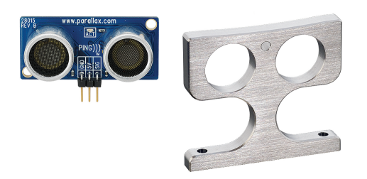
Each of the (4) Ping))) Sensor & Protector Stand Kits includes the following components:
Note: You can use a few zip ties to help keep them neatly in place like shown in the photo below, but you may need more zip ties for this than were provided in the kit. This is optional, but we do recommend having additional zip ties on hand for future Arlo modification.
With the Ping))) and servo subsystems working correctly, we can combine them with motor control to make the cyber:bot roam. This program has several places where you can easily customize it for better performance in your own environment.
This connection diagram (below) shows where to connect each 3-wire Ping))) sensor cable. If you’re looking at the color version, note that each black wire is connected to either GND on the breadboard, or the GND terminal in the servo header. Each of those black wires should also be connected to a Ping))) sensor’s GND pin. The power selection jumper between the P13 and P14 servo ports should also be set to 5V, likewise for the one between P15 and P16.