Many items you use every day have pushbuttons. Cell phones, microwave ovens, TV remotes, and computer keyboards might all have pushbuttons. Can you think of others?
Let's use a common pushbutton circuit and build a program for monitoring it with your microcontroller. Then, let's use a pushbutton's state to control LED circuits. LEDs are just one example of a device you can turn on and off with a microcontroller. Your invention might instead use pushbuttons to control circuits for motors, heating elements, or other devices.
The micro:bit module has two built-in pushbuttons. You can also add more pushbuttons to your cyber:bot on the breadboard. Doing so, you will learn how a pushbutton circuit works.
About Pushbuttons
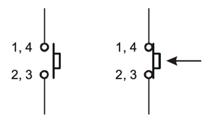
A pushbutton is a device that makes an electrical connection between two of its terminal leads when its button is pressed. When the button is released into its normally-open state, the electrical connection is broken and no current flows through the device. Here is the schematic symbol:
...and here is a drawing that resembles a breadboard-friendly pushbutton:
![]()
Notice that when the button is pushed, all 4 pins are connected. However, when the button is not pushed, legs 1 and 4 are still connected and legs 2 and 3 are still connected.
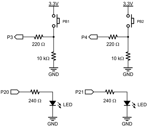
If the pushbutton is pressed, the circuit applies 3.3 V to the I/O pin through the pushbutton, and a small amount of current also passes through the 10 kΩ resistor to ground. When the pushbutton is not pressed, the connection to the 3.3 V supply is broken, and so the circuit applies GND (0 V) to the I/O pin.
Pushbutton and LED Circuits
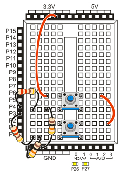
This circuit uses your board's built-in P20 and P21 LEDs, along with two pushbutton circuits you will build onto your breadboard. Use 220 ohm resistors to connect the pushbutton circuits to the cyber:bot I/O pins and use 10 k-ohm resistors to connect the circuits to ground.
Parts
(2) pushbuttons
(2) 220 ohm resistors (red-red-brown)
(2) 10 k-ohm resistors (brown-black-orange)
- Build the two pushbutton circuits shown in the schematic and wiring diagram. We are also using the built-in LEDs on P20 and P21.
Test script: test_pin_3_button
This test script will display the state of the button connected to P3 on the micro:bit module’s display. The display will show a 1 if the button is pressed, or 0 if it is not pressed.
- Enter, save, and flash the script test_pin_3_button.
# test_pin_3_button

from cyberbot import *

while True:
    if bot(3).read_digital() == 0:
        display.show("0")
    elif bot(3).read_digital() == 1:
        display.show("1")
How test_pin_3_button Works
This Python script is all inside of a continuous while True: loop. Inside the loop there is one if statement that checks two conditions.
The first condition that it checks is whether the bot(3).read_digital function is equal to 0. If this is true the micro:bit module will display a 0. The read_digital function checks the input state of the pin, in this case P3. Thus, if the button is not being pressed, the input state at pin 3 is 0.
The second part of the if statement checks to see if the input state is 1 (button pushed), if so the micro:bit module will display a 1.
Did You Know?
Active-high: The pushbutton circuit you are using is called active-high because the pushbutton sends the cyber:bot I/O pin a 3.3 V high signal when pressed (active) or a 0 V low signal when released.
Pull-down: The 10 k-ohm resistor in the schematic is called a pull-down resistor. It’s there so that the I/O pin will detect 3.3 V through the resistor when the button is pressed. If you leave it out, the I/O pin behaves more like an antenna, and nearby electric fields will end up controlling whether 1 or 0 is detected.
Active-low, pull-up: Pushbuttons circuits can also be active-low. All you have to do is swap the pushbutton and 10 k-ohm resistor in the schematic. The pull-down resistor then becomes a pull-up resistor, and the I/O pin will detect 0 V when the button is pressed.
Try This: pin_3_button_LED
Now it is time to control an LED with a pushbutton.
- Change the display.show functions to the write_digital function to turn on the yellow LEDs attached to pin 20 when the button is being pressed.
- Change test_pin_3_button to pin_3_button_LED
- Change display.show("0") to bot(20).write_digital(0) and change display.show("1") to bot(20).write_digital(1).
- Enter, save, and flash the script below:
# pin_3_button_LED

from cyberbot import *

while True:
    if bot(3).read_digital() == 0:
        bot(20).write_digital(0)
    elif bot(3).read_digital() == 1:
        bot(20).write_digital(1)
- Verify that the P20 LED blinks if you press the pushbutton connected to P3, and turns off when you release it.
Your Turn - P21 LED and P4 Pushbutton
Can you make the LED connected to P21 light when the button connected to P4 is pressed?
- Modify your Try This project to test controlling the P21 LED with the P4 pushbutton.
- Save the project, and expand the code so that the P3 button controls the P20 LED and the P4 button controls the P21 LED at the same time.