REMOVE the XBee, WX, or other RADIO MODULE BEFORE your proceed! This tutorial uses the indicator lights for the XBee/WX socket to demonstrate how to toggle pins, and if you leave the radio module plugged in, you will damage both the radio module and Flight Controller!
The Parallax Flight Controller has 3 status LEDs for a radio module plugged into the XBee/WX socket. If there is no radio module plugged into that socket, the LEDs can be turned on and off by the on-board Propeller Microcontroller. Here is part of the schematic for the Flight Controller. If you look carefully, there are 3 LEDs connected to P21, P22, and P23:
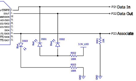
Setting P21 and P22 low will turn on those two LEDs, and Setting P23 high will turn on that LED.
Try This
Now you are ready to edit the firmware on the flight controller to turn LEDs off and on. First, you need to add a few functions to the Flight Controller Firmware.
- Using SimpleIDE, open the flight controller firmware.
- With elev8-main.side open, click on the "Open Project Manager" icon in the lower left corner of the window:
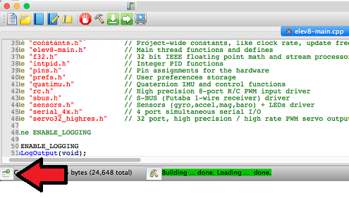
A list of files will appear on the left side of the window.
- Click on elev8-main.cpp to make sure you are editing that file.
- Scroll down until you find the following code (around line 195):
int main()                                    // Main function
{
  Initialize(); // Set up all the objects
- Copy the following code and paste it into elev8-main.cpp BEFORE the main() function:
// Functions to set a pin's direction
void FCsetAsInput( int pinNumber ) { DIRA &= ~( 1 << pinNumber ); }
void FCsetAsOutput( int pinNumber ) { DIRA |= ( 1 << pinNumber ); }

// Functions to set the state of an output pin
void FC_low( int pinNumber ) { OUTA &= ~( 1 << pinNumber ); }
void FC_high( int pinNumber ) { OUTA |= ( 1 << pinNumber ); }
unsigned int FC_toggle( int pinNumber )
{
  OUTA ^= ( 1 << pinNumber );
  return (OUTA >> pinNumber ) & 1;
}

// Function to read an input pin
unsigned int FC_input( int pinNumber )
{
  int mask = 1 << pinNumber;                        // Set up mask
  return (INA & mask) >> pinNumber;                 // Return input state
}
- Copy the following code and paste it into a blank line AFTER the Initialize(); function:
// Set up the 3 pins attached to the LEDs as outputs
FCsetAsOutput(21);
FCsetAsOutput(22);
FCsetAsOutput(23);
- Next, find the following code (near line 530):
void InitSerial(void)
{
  S4_Initialize();

  S4_Define_Port(0, 115200,      30, TXBuf1, sizeof(TXBuf1),      31, RXBuf1, sizeof(RXBuf1));
  S4_Define_Port(1,  57600, XBEE_TX, TXBuf2, sizeof(TXBuf2), XBEE_RX, RXBuf2, sizeof(RXBuf2));

  // Unused ports get a pin value of 32
  S4_Define_Port(2, 19200,       19, TXBuf3, sizeof(TXBuf3),      20, RXBuf3, sizeof(RXBuf3));
  S4_Define_Port(3, 115200, PIN_MOTOR_AUX2, TXBuf4, sizeof(TXBuf4), 32, RXBuf4, sizeof(RXBuf4));

  S4_Start();
}
- Change all of the highlighted values to 32. This prevents the flight controller from trying to use any of those extra pins for serial communication.
The pins in the code above are not necessary for flight, but this does disable communication through the XBee/WX socket.
- Finally, find a blank line after the line UpdateFlightLEDColor(); (near line 660), and paste in the following code:
  if( Radio.Aile < 0 )  // Check the right transmitter stick
  {
    FC_low(21);         // Turn the red LED on
    FC_high(22);        // Turn the left blue LED off
  } else {
    FC_high(21);        // Turn the red LED off
    FC_low(22);         // Turn the left blue LED on
  }

  if( Radio.Elev < 0 )  // Check the right transmitter stick
  {
    FC_low(23);         // Turn the right blue LED off
  } else {
    FC_high(23);        // Turn the right blue LED on
  }
- Save your project.
DO NOT CONNECT YOUR ELEV-8's Battery. Make sure the propellers have been removed from your ELEV-8 quadcopter before continuing.
- Plug your ELEV-8 v3 Flight Controller into your computer and select the corresponding port from the drop-down menu.
- Click the Upload to EEPROM button.
- Turn on your transmitter.
- Move the right stick around to turn the on-board LEDs off and on.
Your Turn
Replace the Radio.Aile and Radio.Elev with some other variables:
- Radio Channels
- Radio.Thro (-1024 to +1024)
- Radio.Rudd
- Radio.Aile
- Radio.Elev
- Radio.Gear
- Radio.Aux1
- Radio.Aux2
- Radio.Aux3
- Sensors
(3-axis gyroscope, 3-axis accelerometer, 3-axis magnetometer, altimeter/pressure sensor, thermometer, and voltmeter connected to the battery)- sens.Temperature (-32768 to +32767, units of 1/16th of a °C, zero = 25°C)
- sens.GyroX (-32768 to +32767, units of 1/16th of a °/second)
- sens.GyroY
- sens.GyroZ
- sens.AccelX (-32768 to +32767, units of 1/4096th of 1 g [9.8 m/s2])
- sens.AccelY
- sens.AccelZ
- sens.MagX (-32768 to +32767, units of 1/4096th of a gauss)
- sens.MagY
- sens.MagZ
- sens.Alt (approx. -1200000 to +30000000, units in mm above sea-level)
- sens.AltRate (units in mm/second, shouldn't exceed ±120000)
- sens.Pressure (0 to +4096000, units of 1/4096th of an hPa, zero = 260 hPa)
- BatteryVolts (units of 1/100th of a volt, 1200 = 12.00 V)
- Motor Speeds
(Width of PWM pulse sent to ESCs in 1/8th μs, not actual motor speeds)- Motor[1] (+8000 to +16000)
- Motor[2]
- Motor[3]
- Motor[4]
- System Counter
- counter (starts at zero, goes up by 1 every 4 milliseconds)