")
Item code: 29133
What It Can Do
- Measures the earth’s magnetic field in three axes, with a 1–2 degree accuracy
- Provides individual readings for each axis, which may be used separately or together for 3D calculations
- Measures raw strength (gauss) of a nearby magnetic source
The 3-Axis Compass module measures magnetic fields in three directions – or axes, labeled X, Y, and Z. In its most simple form, the module can be used as a basic compass to find earth’s magnetic north.
The compass module can also sense the relative strength of a nearby magnetic source, such as those caused by magnets or electric fields. As the sensor detects magnetism in three dimensions, it can determine relative distance and direction to these sources.

The compass is commonly used with a multi-axis accelerometer, where the data from both sensors can provide useful information detailing speed and direction of travel. The Memsic 2125 Dual-axis Accelerometer and MMA7455 3-Axis Accelerometer Module are good companion accelerometers for the 3-Axis Gyroscope module
It may also be used with an accelerometer and 3-axis gyroscope to construct a 9-axis IMU (intertial measurement unit), common in unmanned aerial vehicles, such as drones and quadcopters.
Parts List
- 3-Axis Compass module
- BASIC Stamp HomeWork Board, Propeller BOE, Propeller QuickStart, or Arduino Uno microcontroller (with breadboard, as needed)
- 22 gauge solid conductor hookup wire
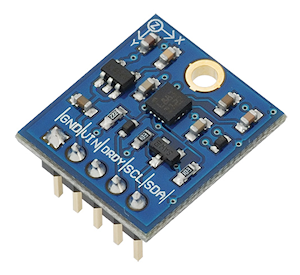
Basic Wiring

- Power Requirements: 2.7 to 6.5 VDC
- Communication Interface: I2C (up to 400 kHz)
- Dimensions: 0.725 x 0.650 in (1.8 x 1.7 cm)
Program KickStarts
The KickStart examples display raw data output for each of the three axes. Values are retrieved from the module using the I2C interface.
BASIC Stamp HomeWork Board

Download BASIC Stamp 2 code for the Compass Module
' {$STAMP BS2}
' {$PBASIC 2.5}

SDA            PIN      0          ' SDA of compass to pin P0
SCL            PIN      1          ' SCL of compass to pin P1

WRITE_Data     CON     $3C         ' Requests Write operation
READ_Data      CON     $3D         ' Requests Read operation
MODE           CON     $02         ' Mode setting register
X_MSB          CON     $03         ' X MSB data output register

X              VAR      Word
Y              VAR      Word
Z              VAR      Word
rawl           VAR      Word
rawh           VAR      Word

' Variables for I2C communications
I2C_DATA       VAR      Byte
I2C_LSB        VAR      Bit
I2C_REG        VAR      Byte
I2C_VAL        VAR      Byte


PAUSE 100                           ' Power up delay
I2C_REG = MODE                      ' Set operating mode to continuous
I2C_VAL = $0
GOSUB I2C_Write_Reg

DO
  GOSUB GetRawReading               ' Get raw Compass reading
  DEBUG HOME, "X = ",11, SDEC x, CR ' Print values
  DEBUG       "Y = ",11, SDEC y, CR
  DEBUG       "Z = ",11, SDEC z, CR
  DEBUG CR
LOOP

GetRawReading:
  PAUSE 400                         ' Wait for new data

  ' Send request to X MSB register
  GOSUB I2C_Start
  I2C_DATA = WRITE_Data
  GOSUB I2C_Write
  I2C_DATA = X_MSB
  GOSUB I2C_Write
  GOSUB I2C_Stop

  'Get data from register (6 bytes total, 2 bytes per axis)
  GOSUB I2C_Start
  I2C_DATA = READ_Data
  GOSUB I2C_Write

  ' Get X
  GOSUB I2C_Read
  rawH = I2C_Data
  GOSUB I2C_ACK
  GOSUB I2C_Read
  rawL = I2C_Data
  GOSUB I2C_ACK
  X = (rawH << 8) | rawL

  ' Get Z
  GOSUB I2C_Read
  rawH = I2C_Data
  GOSUB I2C_ACK
  GOSUB I2C_Read
  rawL = I2C_Data
  GOSUB I2C_ACK
  Z = (rawH << 8) | rawL

  ' Get Y
  GOSUB I2C_Read
  rawH = I2C_Data
  GOSUB I2C_ACK
  GOSUB I2C_Read
  rawL = I2C_Data
  GOSUB I2C_NACK
  Y = (rawH << 8) | rawL

  GOSUB I2C_Stop

RETURN


'---------I2C functions------------
' Set I2C_REG & I2C_VAL before calling this
I2C_Write_Reg:
  GOSUB I2C_Start
  I2C_DATA = WRITE_DATA
  GOSUB I2C_Write
  I2C_DATA = I2C_REG
  GOSUB I2C_Write
  I2C_DATA = I2C_VAL
  GOSUB I2C_Write
  GOSUB I2C_Stop
RETURN

' Set I2C_REG before calling this, I2C_DATA will have result
I2C_Read_Reg:
  GOSUB I2C_Start
  I2C_DATA = WRITE_DATA
  GOSUB I2C_Write
  I2C_DATA = I2C_REG
  GOSUB I2C_Write
  GOSUB I2C_Stop
  GOSUB I2C_Start
  I2C_DATA = READ_DATA
  GOSUB I2C_Write
  GOSUB I2C_Read
  GOSUB I2C_NACK
  GOSUB I2C_Stop
RETURN

I2C_Start:
  LOW SDA
  LOW SCL
RETURN

I2C_Stop:
  LOW   SDA
  INPUT SCL
  INPUT SDA
RETURN

I2C_ACK:
  LOW   SDA
  INPUT SCL
  LOW   SCL
  INPUT SDA
RETURN

I2C_NACK:
  INPUT SDA
  INPUT SCL
  LOW   SCL
RETURN

I2C_Read:
  SHIFTIN SDA, SCL, MSBPRE, [I2C_DATA]
RETURN

I2C_Write:
  I2C_LSB = I2C_DATA.BIT0
  I2C_DATA = I2C_DATA / 2
  SHIFTOUT SDA, SCL, MSBFIRST, [I2C_DATA7]
  IF I2C_LSB THEN INPUT SDA ELSE LOW SDA
  INPUT SCL
  LOW SCL
  INPUT SDA
  INPUT SCL
  LOW SCL
RETURN
When this program is run, the BASIC Stamp Debug Terminal will automatically open.
Propeller BOE and Propeller QuickStart

Propeller BOE Wiring Diagram

Propeller QuickStart Wiring Diagram
Download Propeller Spin code for the Compass Module
OBJ

    pst       :   "FullDuplexSerial"   ' Comes with Propeller Tool

CON

  _clkmode      = xtal1 + pll16x
  _clkfreq      = 80_000_000

  datapin  = 1         ' SDA of compass to pin P1
  clockPin = 0         ' SCL of compass to pin P0

  WRITE_DATA     = $3C ' Requests Write operation
  READ_DATA      = $3D ' Requests Read operation
  MODE           = $02 ' Mode setting register
  OUTPUT_X_MSB   = $03 ' X MSB data output register

VAR

  long x
  long y
  long z

PUB Main

  waitcnt(clkfreq/100_000 + cnt)     ' Power up delay
  pst.start(31, 30, 0, 115200)
  SetCont
  repeat
    SetPointer(OUTPUT_X_MSB)
    getRaw                           ' Gather raw data from compass
    pst.tx(1)
    ShowVals

PUB SetCont
  ' Sets compass to continuous output mode

  start
  send(WRITE_DATA)
  send(MODE)
  send($00)
  stop

PUB SetPointer(Register)
  ' Start pointer at user specified register (OUT_X_MSB)

  start
  send(WRITE_DATA)
  send(Register)
  stop

PUB GetRaw
  ' Get raw data from continuous output

  start
  send(READ_DATA)
  x := ((receive(true) << 8) | receive(true))
  z := ((receive(true) << 8) | receive(true))
  y := ((receive(true) << 8) | receive(false))
  stop
  ~~x
  ~~z
  ~~y
  x := x
  z := z
  y := y

PUB ShowVals
  ' Display XYZ compass values

  pst.str(string("X="))
  pst.dec(x)
  pst.str(string(", Y="))
  pst.dec(y)
  pst.str(string(", Z="))
  pst.dec(z)
  pst.str(string("    "))

PRI send(value)

  value := ((!value) >< 8)

  repeat 8
    dira[dataPin]  := value
    dira[clockPin] := false
    dira[clockPin] := true
    value >>= 1

  dira[dataPin]  := false
  dira[clockPin] := false
  result         := !(ina[dataPin])
  dira[clockPin] := true
  dira[dataPin]  := true

PRI receive(aknowledge)

  dira[dataPin] := false

  repeat 8
    result <<= 1
    dira[clockPin] := false
    result         |= ina[dataPin]
    dira[clockPin] := true

  dira[dataPin]  := aknowledge
  dira[clockPin] := false
  dira[clockPin] := true
  dira[dataPin]  := true

PRI start

  outa[dataPin]  := false
  outa[clockPin] := false
  dira[dataPin]  := true
  dira[clockPin] := true

PRI stop

  dira[clockPin] := false
  dira[dataPin]  := false
To view the results of the demonstration, after uploading is complete run the Parallax Serial Terminal from the Run menu or press F12. Click the Enable button, and momentarily depress the Reset button on the Propeller QuickStart board to restart the program.
Arduino Uno

Download Arduino Code for the Compass Module
#include <Wire.h>

#define Addr 0x1E               // 7-bit address of HMC5883 compass

void setup() {
  Serial.begin(9600);
  delay(100);                   // Power up delay
  Wire.begin();

  // Set operating mode to continuous
  Wire.beginTransmission(Addr);
  Wire.write(byte(0x02));
  Wire.write(byte(0x00));
  Wire.endTransmission();
}

void loop() {
  int x, y, z;

  // Initiate communications with compass
  Wire.beginTransmission(Addr);
  Wire.write(byte(0x03));       // Send request to X MSB register
  Wire.endTransmission();

  Wire.requestFrom(Addr, 6);    // Request 6 bytes; 2 bytes per axis
  if(Wire.available() <=6) {    // If 6 bytes available
    x = Wire.read() << 8 | Wire.read();
    z = Wire.read() << 8 | Wire.read();
    y = Wire.read() << 8 | Wire.read();
  }

  // Print raw values
  Serial.print("X=");
  Serial.print(x);
  Serial.print(", Y=");
  Serial.print(y);
  Serial.print(", Z=");
  Serial.println(z);

  delay(500);
}
To view the results of the demonstration, after uploading is complete click the Serial Monitor icon in the Arduino IDE. This displays the Serial Monitor window. Momentarily depress the Reset button on the Arduino board to restart the sketch.
For More Information
- 3-Axis Compass (#29133) data sheet and application notes
- More information on magnetometers and other forms of digital compasses may be found on Wikipedia: Magnetometer
- Combine the 3-axis compass with the Memsic 2125 Dual-Axis Accelerometer, or MM7455 3-Axis Accelerometer
- Combine the 3-axis compass with the Parallax MMA7455 3-Axis Accelerometer Module and Gyroscope Module 3-Axis L3G4200D to create a 9-axis inertial momentum unit (IMU)