")
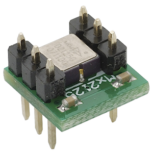
Item code: 28017
What It Can Do
- Measures tilt in two axes: forward and back, or side to side
- Registers sudden changes in motion
- Detects even small amounts of vibration and motion
The Memsic 2125 Dual-axis Accelerometer is sensitive to the gravitational pull of the earth, allowing it to measure tilt, vibration, motion, and acceleration. The sensor provides independent outputs for two axes, labeled X and Y:
- The X axis measures tilt or acceleration forward and back (direction of arrow)
- The Y axis measures tilt or acceleration side to side

The Memsic 2125 module registers the constant pull of Earth’s gravity. This is specified as 1g (g for gravity). For the Memsic sensor, the value of 1g is always some positive number, and is about half way between the highest and lowest readings the module is capable of reporting.
With additional math, you can use the values provided by the accelerometer to convert to actual g-forces or degrees of tilt. See the documentation page for the Memsic 2125 (refer to For More Information, below) for further details.
As a tilt sensor, the Memsic 2125 detects when the module is not level. The output of the sensor indicates the amount of inclination. As a acceleration or vibration sensor, the sensor measures the g-forces acting on it. The greater the g-force, the higher the acceleration or vibration.
The X and Y axis output of the Memsic 2125 is a pulse that has a period of (that is, it repeats) 100 times a second (100 Hz). The width of the pulse represents the instantaneous g-force. By measuring the width of the pulse, you can derive – with high accuracy – the g-force of either axis. The example programs in this KickStart demonstrate this process.

Parts List
- Memsic 2125 Dual-axis Accelerometer
- BASIC Stamp HomeWork Board, Propeller Board of Education, Propeller QuickStart, or Arduino Uno microcontroller
- 22 gauge solid conductor hookup wire
- (2) 220 Ω resistors, 1/8 or 1/4 watt, 5-10% tolerance (BASIC Stamp 2)
Basic Wiring

- Power requirements: 3.3 to 5 VDC
- Communication: TTL/CMOS compatible 100 Hz PWM output signal with duty cycle proportional to acceleration
- Dimensions: 0.42 x 0.42 x 0.45 in (10.7 x 10.7 x 11.8 mm)
Program KickStarts
The example programs display the current X and Y values of the Memsic 2125 accelerometer in a terminal/debug window. The program is set to repeat indefinitely. Demonstrate the operation of the module by tilting it forward and back, and side to side.
For the Propeller and Arduino, the values displayed in the window represent the width of the pulses, in microseconds. For the BASIC Stamp 2, the width value is in units, where one unit is equal to 2 microseconds.
BASIC Stamp HomeWork Board

Download BASIC Stamp 2 code for the Memsic 2125 Accelerometer
'{$STAMP BS2}
'{$PBASIC 2.5}
x   VAR   Word
y   VAR   Word
DEBUG CLS
DO
  PULSIN 6, 1, x                        'Read X axis
  PULSIN 7, 1, y                        'Read Y axis
  DEBUG HOME, DEC4 ? X, DEC4 ? Y        'Display values
  PAUSE 100
LOOP
When this program is run the BASIC Stamp Debug Terminal will automatically open.
At 1g (no tilt) the value of the X and Y outputs is approximately 2500. This value increases or decreases with forward or back tilt.
Propeller BOE and Propeller QuickStart

Propeller BOE Wiring Diagram

Propeller QuickStart Wiring Diagram
Download Propeller Spin code for the Memsic 2125 Accelerometer
OBJ

  pst     : "FullDuplexSerial"
  MM2125  : "Memsic2125"

CON

  _clkmode = xtal1 + pll16x
  _xinfreq = 5_000_000

  xIn = 0
  yIn = 1

PUB Go | x,y

  pst.start(31, 30, 0, 115200)
  MM2125.start(xIn, yIn)        ' Initialize Memsic 2125

  repeat
    x := MM2125.Mx		' Read X axis
    y := MM2125.My		' Read Y axis

    pst.dec(x / 100)		' Display X axis, divided by 100
    pst.tx(9)                   ' Tab
    pst.dec(y / 100)            ' Display Y axis, divided by 100
    pst.tx(13)                  ' New line
    WaitCnt(ClkFreq / 2 + Cnt)
This program uses the Parallax Serial Terminal and Memsic2125 object libraries, which are included with the Propeller Tool software download.
To view the results of the demonstration, after uploading is complete run the Parallax Serial Terminal from the Run menu, or press F12. Momentarily depress the Reset button on the Propeller QuickStart board to restart the program.
At 1g (no tilt) the value of the X and Y outputs is approximately 5000. This value increases or decreases with forward or back tilt.
Arduino Uno

Download Arduino Code for the Memsic 2125 Accelerometer
const int xIn = 2;              // X output
const int yIn = 3;              // Y output

void setup() {
  Serial.begin(9600);
}

void loop() {
  // variables to read the pulse widths:
  int pulseX, pulseY;

  pulseX = pulseIn(xIn,HIGH);  // Read X pulse
  pulseY = pulseIn(yIn,HIGH);  // Read Y pulse

  // Display result
  Serial.print(pulseX);	       // Display X and Y values
  Serial.print("\t");
  Serial.println(pulseY);

  delay(200);
}
To view the results of the demonstration, after uploading is complete click the Serial Monitor icon in the Arduino IDE. This displays the Serial Monitor window. Momentarily depress the Reset button on the Arduino board to restart the sketch.
At 1g (no tilt) the value of the X and Y outputs is approximately 5000. This value increases or decreases with forward or back tilt.
For More Information
- View the Memsic 2125 accelerometer (#28017) full documentation.
- Check out the Stamps in Class Mini Projects available in the Projects section of this site for many Memsic 2125 accelerometer projects.
- See Accelerometers on Wikipedia for additional information on g-forces, types of accelerometers, and accelerometer measurement techniques.