Skip to content
Parallax Learn

Parallax Learn

  • Welcome
  • Tutorials
        • Tutorial Series head tag

          Tutorial Series
        • Tutorial Series

          The special, classroom-ready series pages are organized collections of tutorials for our most popular hardware and/or languages. The tutorials for each topic are conveniently accessible from a single page, shown in the order it is recommended that they be completed.
        • Robotics Series Head tag

          Robotics Series
        • Robotics Series

          • Artificial Intelligence
          • Cybersecurity: Radio Data tutorialCybersecurity
          • cyber:bot + Python
          • cyber:bot + MakeCode
          • Boe-Bot Tutorial SeriesBoe-Bot
          • Arduino Shield-Bot
          • ActivityBot with C TutorialsActivityBot + C
          • ActivityBot with BlocklyProp Tutorial SeriesActivityBot + BlocklyProp
          • Scribbler 3 Tutorial SeriesScribbler 3
        • Electronics & Programming Series Head tag

          Electronics & Programming Series
          • BS2 Board of Education Tutorial SeriesBS2 Board of Education
          • Propeller C-Language BasicsPropeller C Basics
          • FLiP Try-It Kit C Tutorial SeriesFLiP Try-It Kit + C
          • FLiP Try-It Kit BlocklyProp TutorialsFLiP Try-It Kit + BlocklyProp
          • Badge WX Tutorial SeriesBadge WX
          • Propeller BlocklyProp Basics and ProjectsPropeller BlocklyProp Basics
          • View All Tutorial Series »
        • Browse Tutorials
        • Browse Tutorials

          Individual tutorials sorted by robot or kit, and language.
        • By Robot or Kit
          • ActivityBot
          • SumoBot WX
          • Boe-Bot
          • Shield-Bot
          • cyber:bot
          • Badge WX
          • ELEV-8
          • ARLO
        • By Language
        • By Language

          • Propeller C
          • Arduino
          • BlocklyProp
          • PBASIC
          • Python
          • MakeCode
          • View All Tutorials »
  • Educators
  • Reference
  • Downloads
  • Home
  • All Courses

Arlo Robot Assembly Guide

Curriculum

  • 1 Section
  • 47 Lessons
  • Lifetime
Expand all sectionsCollapse all sections
  • Arlo Robot Assembly Guide
    47
    • 1.1
      Section 0 – Getting Ready to Build Arlo
    • 1.2
      Section 1 – Motor Mount and Wheel Kit Assembly
    • 1.3
      Step 1 – Axle Assemblies
    • 1.4
      Step 2 – Motor to Bearing Block Assembly
    • 1.5
      Step 3 – Drive Axle Pin
    • 1.6
      Step 4 – Bearing Block and Axle
    • 1.7
      Step 5 – Soldering the Encoder Connectors
    • 1.8
      Step 6 – Encoder Cables
    • 1.9
      Step 7 – Encoder Assemblies
    • 1.10
      Step 8 – Drive Wheels
    • 1.11
      Step 9 – Wheel Assemblies to Drive Shaft
    • 1.12
      Section 2 – Caster Wheel Kits
    • 1.13
      Step 10 – Swivel Rod and Mounting Plate
    • 1.14
      Step 11 – Swivel Block
    • 1.15
      Step 12 – Flange Bearings
    • 1.16
      Step 13 – Shaft Collar and Swivel Post
    • 1.17
      Section 3 – Mounting Wheel Assemblies
    • 1.18
      Step 14 – Lay Out the Parts
    • 1.19
      Step 15 – Motor Mounts to Arlo Base
    • 1.20
      Step 16 – Casters to Arlo Base
    • 1.21
      Step 17 – Screws and Standoffs
    • 1.22
      Section 4 – Arlo Power Distribution Board
    • 1.23
      Step 18 – Low-Profile Components
    • 1.24
      Step 19 – Diodes
    • 1.25
      Step 20 – Fuse Holders
    • 1.26
      Step 21 – Terminal Blocks
    • 1.27
      Step 22 – Switch Terminals
    • 1.28
      Step 23 – Charging Power Jack
    • 1.29
      Step 24 – Voltage Regulators and Heat Sinks
    • 1.30
      Step 25 – Polarized Capacitors
    • 1.31
      Step 26 – Switch Plate
    • 1.32
      Step 27 – Switch Plate Assembly to PDB
    • 1.33
      Section 5 – Batteries and Battery Tray
    • 1.34
      Step 28 – Prepare Battery and Tray
    • 1.35
      Step 29 – Batteries and Tray
    • 1.36
      Section 6 – Assembling and Mounting the Ping))) Sensors
    • 1.37
      Step 30 – Light Pipe and Protector Stands
    • 1.38
      Step 31 – Attach Ping)))s to Stands
    • 1.39
      Section 7 – Control Components and DHB-10 Connections
    • 1.40
      Step 32 – Arlo Power Distribution Board
    • 1.41
      Step 33 – DHB-10 and Control Board
    • 1.42
      Section 8 – Arlo Top Deck
    • 1.43
      Step 34 – Wiring the DHB-10 Power Connections
    • 1.44
      Step 35 – Wire PDB to Battery
    • 1.45
      Step 36 – Prep the Barrel Jack Connection
    • 1.46
      Step 37 – Connecting Power & Encoders
    • 1.47
      Step 38 – Mount Top Deck

Step 8 – Drive Wheels

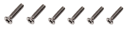
Each of the two aluminum wheel assemblies is comprised of: (1) precision machined two-piece split-rim set, (1) inner-tube, (1) rubber tire, and (6)  flat-head 4-40 x ½” screws.              

  • Begin by inflating the inner tubes with a hand operated air pump – DO NOT USE A COMPRESSOR!  Add just enough air to make them round, but not under any pressure. 

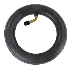
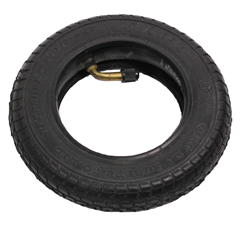
  • Insert the tube(s) into the tires.  This will help keep the tube and tread in alignment as you’re “sandwiching” the split rim wheel system together (above).

Each rim set consists of: (1) main rim, (1) rim ring, and (6) flathead #4-40 x ½” long machine screws.

WARNING! Never, ever put your fingers through the holes in the rims once the wheels are assembled. It may be tempting to carry an assembled Arlo by the wheel, but this poses a grave hazard to your fingers should the motors accidentally move the wheels.

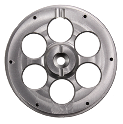
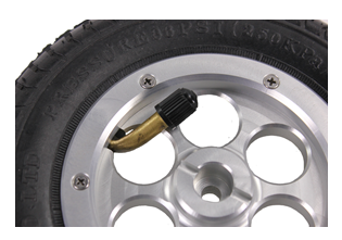
  • Place the main rim over the tube’s valve stem, being sure to line up the rim’s stem notch as shown below.  Push it down tight so that the rim is well seated into the rubber tire. 

You can choose whether to have the valve stem easily accessible from the outside of the robot (not shown), which makes it slightly easier to fill the tires if they ever need it. However, we recommend the “cleaner looking” appearance of having the stem “tucked” behind the rim, as shown here.

If you ever need to add air (very rare, if ever), you can simply remove the single bolt that holds the tire onto the motor drive axle to access the valve stem. The rim set uses #4-40 x ½” long flat head machine screws which screw directly into tapped holes from the “inside” of the aluminum main rim section.  This provides for a very clean look when mounted on the Arlo Base.

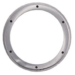
  • Insert a screw into each of the holes in the inner rim.  Then, place the inner rim on the tire as shown, aligning the screws with the holes in the main rim.

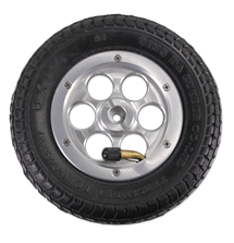
The rims are precision-machined to hold the tires securely.  You may have to push firmly to get the rim to fully seat itself into the hub of the rubber tire.  Repeat this step for the other drive wheel.

Unless your Arlo is going to be carrying very heavy loads, there is no need to inflate the tires to their full rated capacity. Even though the tire sidewall indicates “35PSI”, we recommend no more than 10 to 15 psi for optimum traction, load carrying capacity, and shock absorption.  We HIGHLY ADVISE using a bicycle hand pump (instead of a powered air compressor) to inflate the tires since the tube capacity is so small.  It is very easy (and dangerous!) to over-inflate the tire using a powered air compressor.

Secure the Rims:  Rim assembly best practice is to get all of the screws started into their respective threaded holes without fully securing any of them.  Then, tighten each one slightly and continue this around the circle progressively tightening each screw, which will bring the two rim sections together evenly.  Also, be sure to not pinch or bind the inner-tube while bringing the assembly together.


Printer-friendly version
Step 7 – Encoder Assemblies
Prev
Step 9 – Wheel Assemblies to Drive Shaft
Next

DISCUSSION FORUMS | PARALLAX INC. STORE

About | Terms of Use | Feedback: learn@parallax.com | Copyright©Parallax Inc. 2024

© 2026 Parallax Learn • Built with GeneratePress