Skip to content
Parallax Learn

Parallax Learn

  • Welcome
  • Tutorials
        • Tutorial Series head tag

          Tutorial Series
        • Tutorial Series

          The special, classroom-ready series pages are organized collections of tutorials for our most popular hardware and/or languages. The tutorials for each topic are conveniently accessible from a single page, shown in the order it is recommended that they be completed.
        • Robotics Series Head tag

          Robotics Series
        • Robotics Series

          • Artificial Intelligence
          • Cybersecurity: Radio Data tutorialCybersecurity
          • cyber:bot + Python
          • cyber:bot + MakeCode
          • Boe-Bot Tutorial SeriesBoe-Bot
          • Arduino Shield-Bot
          • ActivityBot with C TutorialsActivityBot + C
          • ActivityBot with BlocklyProp Tutorial SeriesActivityBot + BlocklyProp
          • Scribbler 3 Tutorial SeriesScribbler 3
        • Electronics & Programming Series Head tag

          Electronics & Programming Series
          • BS2 Board of Education Tutorial SeriesBS2 Board of Education
          • Propeller C-Language BasicsPropeller C Basics
          • FLiP Try-It Kit C Tutorial SeriesFLiP Try-It Kit + C
          • FLiP Try-It Kit BlocklyProp TutorialsFLiP Try-It Kit + BlocklyProp
          • Badge WX Tutorial SeriesBadge WX
          • Propeller BlocklyProp Basics and ProjectsPropeller BlocklyProp Basics
          • View All Tutorial Series »
        • Browse Tutorials
        • Browse Tutorials

          Individual tutorials sorted by robot or kit, and language.
        • By Robot or Kit
          • ActivityBot
          • SumoBot WX
          • Boe-Bot
          • Shield-Bot
          • cyber:bot
          • Badge WX
          • ELEV-8
          • ARLO
        • By Language
        • By Language

          • Propeller C
          • Arduino
          • BlocklyProp
          • PBASIC
          • Python
          • MakeCode
          • View All Tutorials »
  • Educators
  • Reference
  • Downloads
  • Home
  • All Courses
  • Breadboard Setup and Testing for micro:bit

Breadboard Setup and Testing for micro:bit

Resistor Codes & Electron Flow

Resistor Color Codes

One of the most common identification schemes for resistors is the four-band color code.  Each of the four color bands on your resistors represents a value. 

To read a resistor, position it so that the fourth band, which is going to be gold, silver or blank, is on the right.  The left two bands are the first two digits in its resistance value.  The third band is the number of zeros to append to the resistance value. 

You can use the digits in the Resistor Color Codes chart to figure out what digit each color indicates.  The fourth band is the tolerance.  That’s a measure of how far the parts actual resistance might be from what the color bands say.

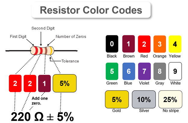
In the example of a resistor with red-red-brown-gold color bands, the first two digits are red, red.  Since red is the digit 2, the red-red bands mean 22.  The third band is the number of zeros to add to the value.  Since the brown band is 1, it means add one zero, for 220 Ω.  The gold color band means the resistor has a 5% tolerance.  5% of 220 Ω is 11 Ω, so the resistor’s actual value will be somewhere between 209 and 231 Ω.

Other Color Codes: The rules in this resistor ID table cover the four-band resistors in your kit.  There are more digit and tolerance options.  For more complete color band ID tables, check the Electronic color code at Wikipedia.


Electron Flow

Look at the picture of a battery-powered LED circuit below. A battery contains chemicals with an excess of electrons connected to its (-) terminal and chemicals that are missing electrons connected to its (+) terminal. 

With the LED circuit connected, the electrons escape molecules in the chemical where they are already overcrowded, flow from the battery’s (-) terminal through the circuit to its (+) terminal, and then join the chemical with molecules that are lacking electrons.  The molecules that lose their extra electrons go from being negatively charged (-) to being neutral (n).  Likewise, when the positively charged (+) molecules that are lacking electrons gain an electron, they also become neutral (n).

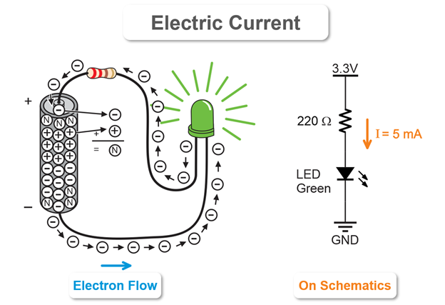
Current is represented quite differently on a schematic.  It is typically indicated by an arrow pointing from the higher voltage to the lower voltage.  There might be some number of amps (A) or milliamps (mA) next to the arrow.  It might even contain an expression like I = 5 mA.  The variable I is commonly used as the variable to store current in calculations.  


Printer-friendly version
How the LED Circuit Works
Prev
Try This – Change the Resistor
Next

DISCUSSION FORUMS | PARALLAX INC. STORE

About | Terms of Use | Feedback: learn@parallax.com | Copyright©Parallax Inc. 2024

© 2025 Parallax Learn • Built with GeneratePress