Assembling the Project Components
Building The Project
Before You Start:
Download the Code files and Schematic Images
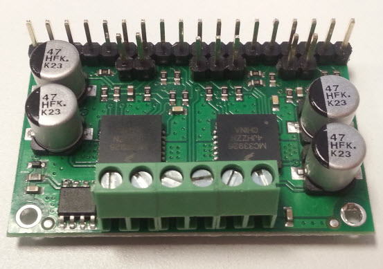
The first step is to solder a row of pins onto the motor driver board. The Pololu MC33926 board comes with 25 breakaway male header pins. Breakaway 18 pins from the header and insert them into the pin slots on the driver board and solder them on. You can solder the remaining pins onto the board; however, they are optional for this application. (Make sure you wear your safety goggles.) Now solder the 3 terminal blocks on the opposite side of the board. The terminal block’s opening should be facing away from the board. (See image below.)
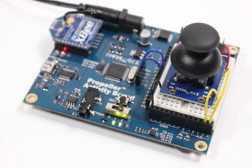
Now it’s time to build the joystick circuit on one of your Activity Boards. Click here to view the wiring diagram from the Propeller C Joystick tutorial and use it to build your “Joystick” circuit. To attach the XBee modules simply align their pins with the Activity Board ’s socket located over the SD card slot. The two angled edges of the XBee should be facing away from the Activity Board. (See image below.)
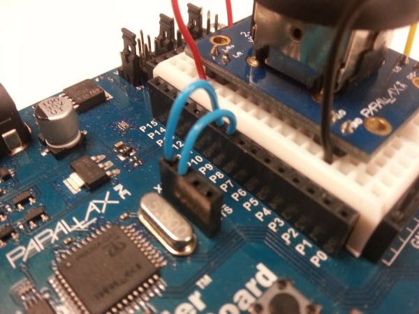
After attaching the XBees you will need to connect two jumper wires. One jumper connects the DO pin (Data Out) to pin 9 and the second jumper connects DI (Data In) to pin 8. Make sure that both Activity Boards have XBees installed, and jumpers connected to DO and DI as shown in the following image.
The next step is to connect the motor driver board to your second Activity Board. In this step it is wise to go slow since it’s easy to make a wiring mistake when making this many connections. Always make sure your board is disconnected from its power source before connecting any wiring. Use the legend below and schematic images included in the code download (at the top of the page) to guide you on each connection.
Legend:
- AB = Activity Board
- MC = Pololu MC33926Motor Driver Board
MOTOR 1:
- MC Vin to AB Vin (Note: Vin is the pin near the top right corner of AB between P15 and P16)
- MC GND to AB GND
- MC VDD to AB 3.3V
- MC M1IN2 to AB P5
- MC M1IN1 to AB P4
- MC(PWM)/M1D2 to AB 3.3V
- MC(PWM)M1D1 to AB GND
- MC EN to AB 3.3V
- M1OUT1 to motor RED
- M1OUT2 to motor BLACK
MOTOR 2 :
- MC M2IN2 to AB P3
- MC M2IN1 to AB P2
- MC PWM M2D2 to 3.3V
- MC PWM M2D1 to GND
- M2OUT1 to motor RED
- M2OUT2 to motor BLACK
For these connections, use the AB-Pololu-Schematic-05.jpg file in the code download zip.
Take one DC motor and connect M1OUT1 to its red input and M1OUT2 to its black input. Now take the second motor and connect M2OUT1 to its red input and M2OUT2 to the its black input.