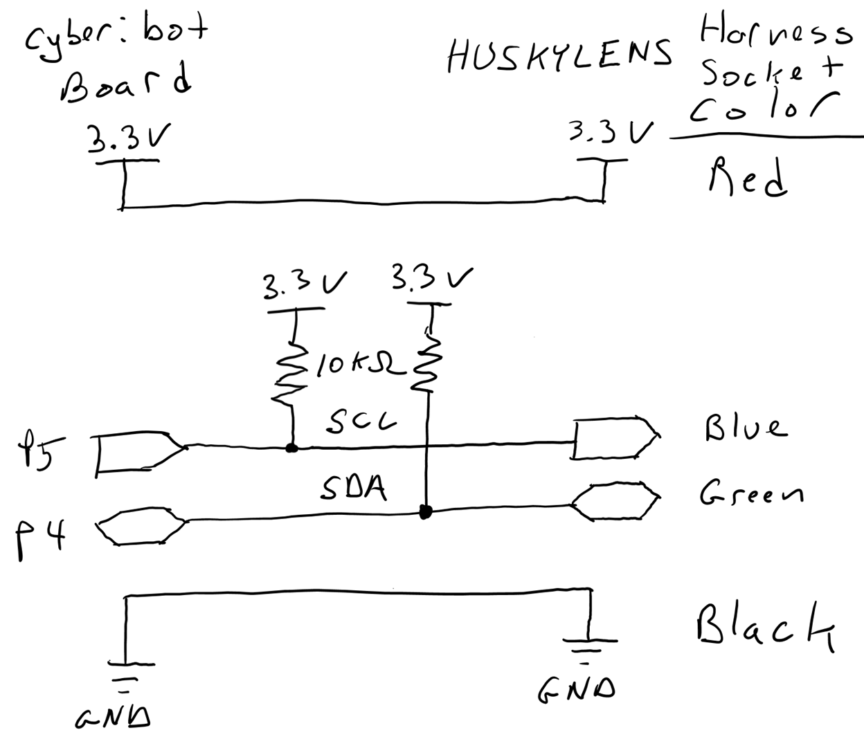
Wire it: Connect with I²C
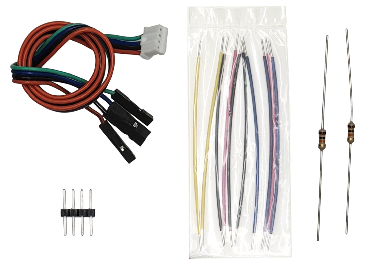
Parts
(1) JST plug to 4-socket cable
(1) Header: 4-pin
(2) Resistors: 10 kΩ (brown-black-orange-gold)
(4) Jumper wires
Recommended: 1 red, 1 black, 2 blue
Circuit
Build the circuit exactly as shown using the two 10 kΩ resistors, four jumper wires, and the four-post header.
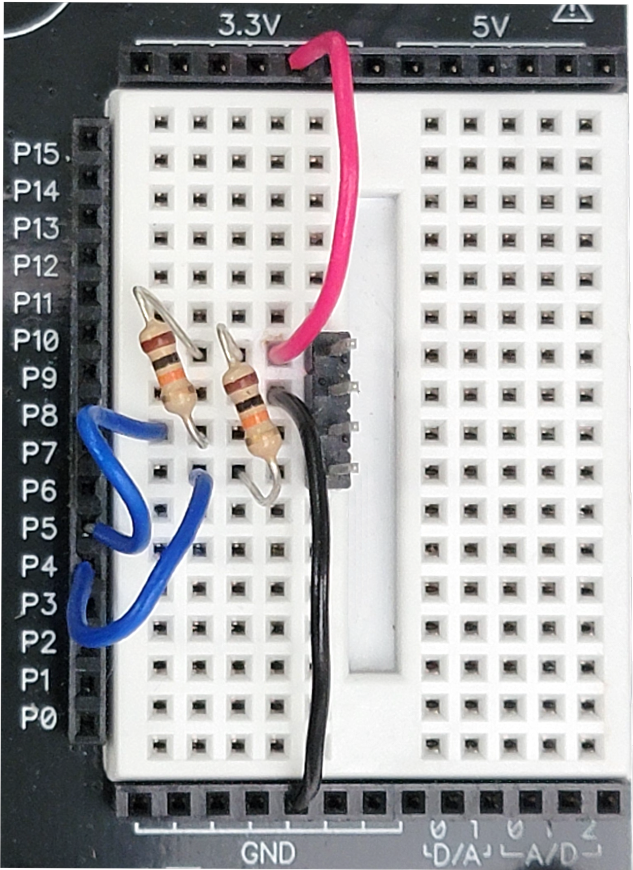
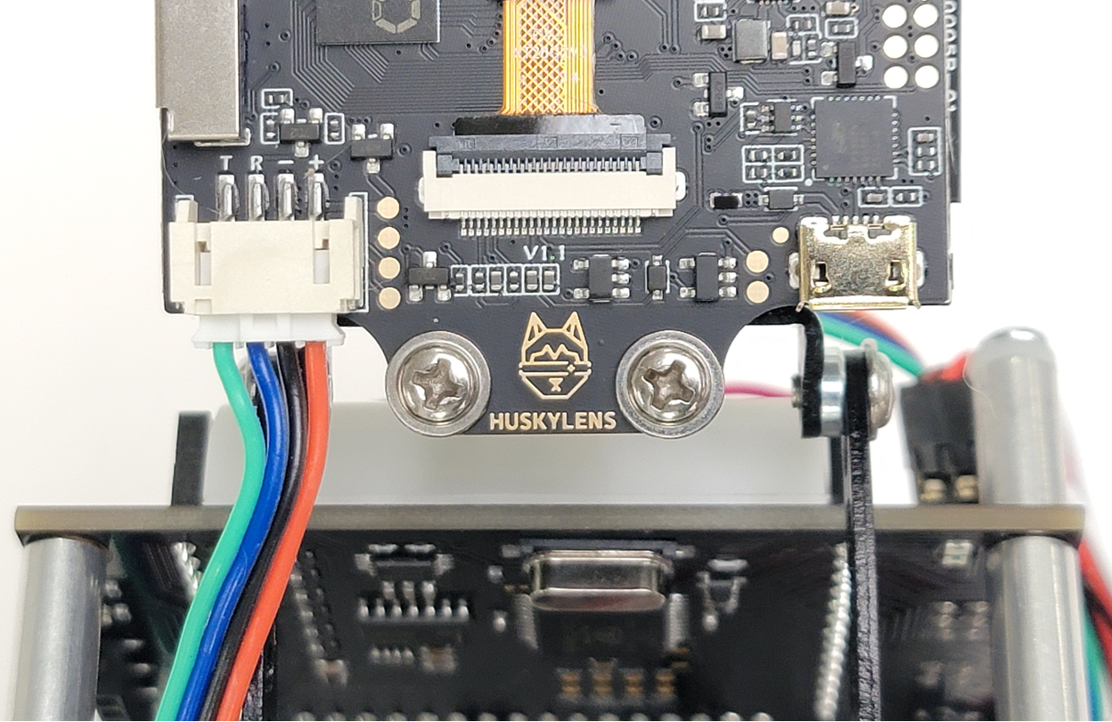
Connect the 4-wire harness’ sockets to the 4-pin header as shown: Red, black, blue, green
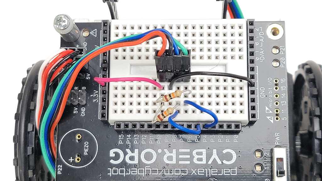
Connect the JST plug end of the cable to the HUSKYLENS JST socket.
About the Circuit
The four colored wires that connect the cyber:bot to the HUSKYLENS are:
- Red: 3.3 V power
- Blue: I²C serial clock (SCL) signal
- Green: I²C serial data (SDA) signal
- Black: Common ground
The micro:bit exchanges data with the HUSKYLENS with a communication protocol called I²C (pronounced eye-squared-see). P5 is connected to the I²C SCL line and P4 to SDA.