cyber:bot Wheel Speed Control
In this activity, you will write scripts that control servo speeds and directions.
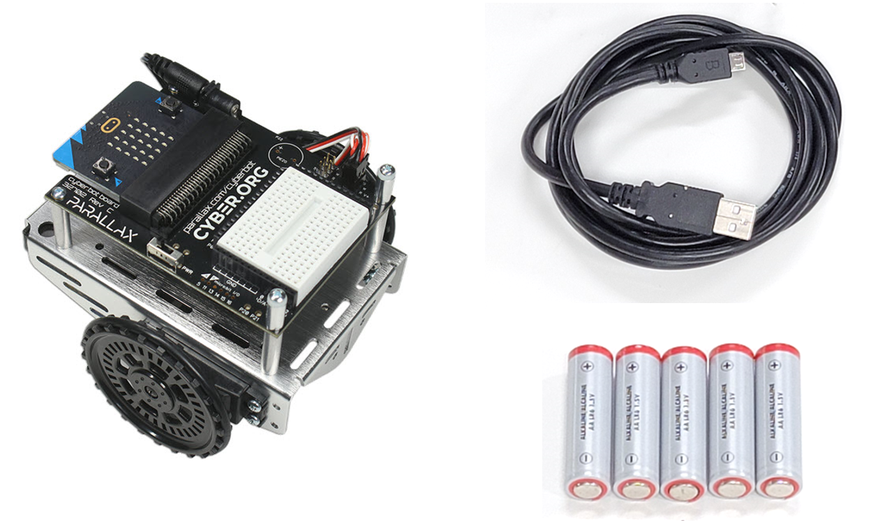
Parts
(1) USB A to Micro-B cable.
(1) cyber:bot robot, fully assembled
(5) AA batteries
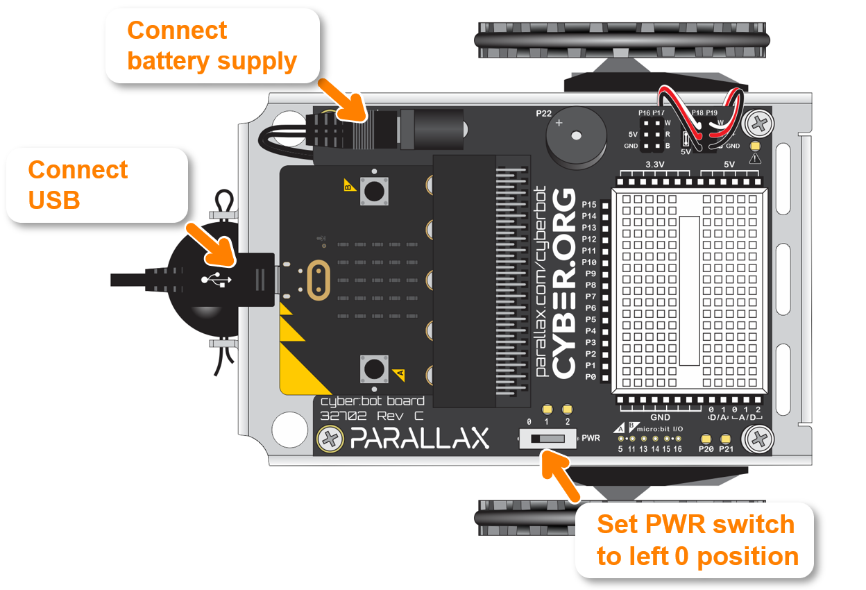
Setup
- Set the PWR switch to 0.
- Connect the cyber:bot robot’s micro:bit to the computer with the USB cable.
- Load batteries into the cyber:bot robot’s battery holder.
- Make sure the battery holder’s barrel plug is plugged into the cyber:bot board’s barrel jack.
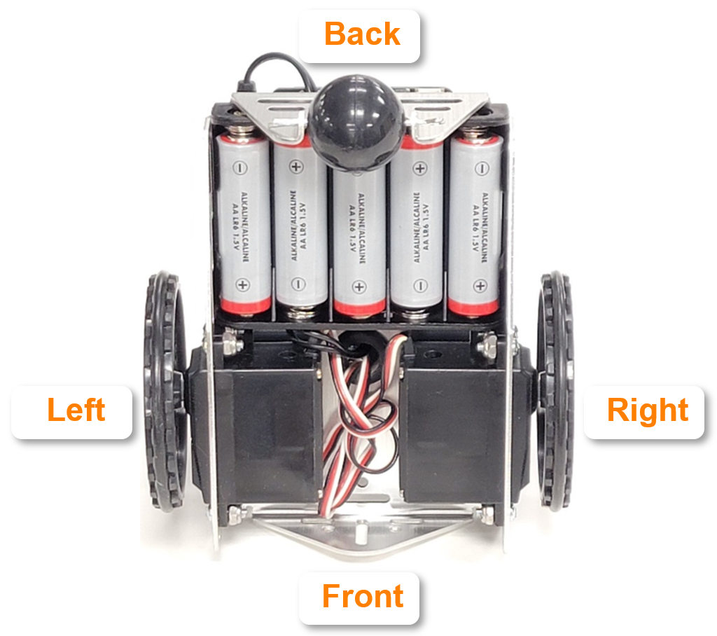
- Set the cyber:bot Robot on its front so that the wheels can turn freely.
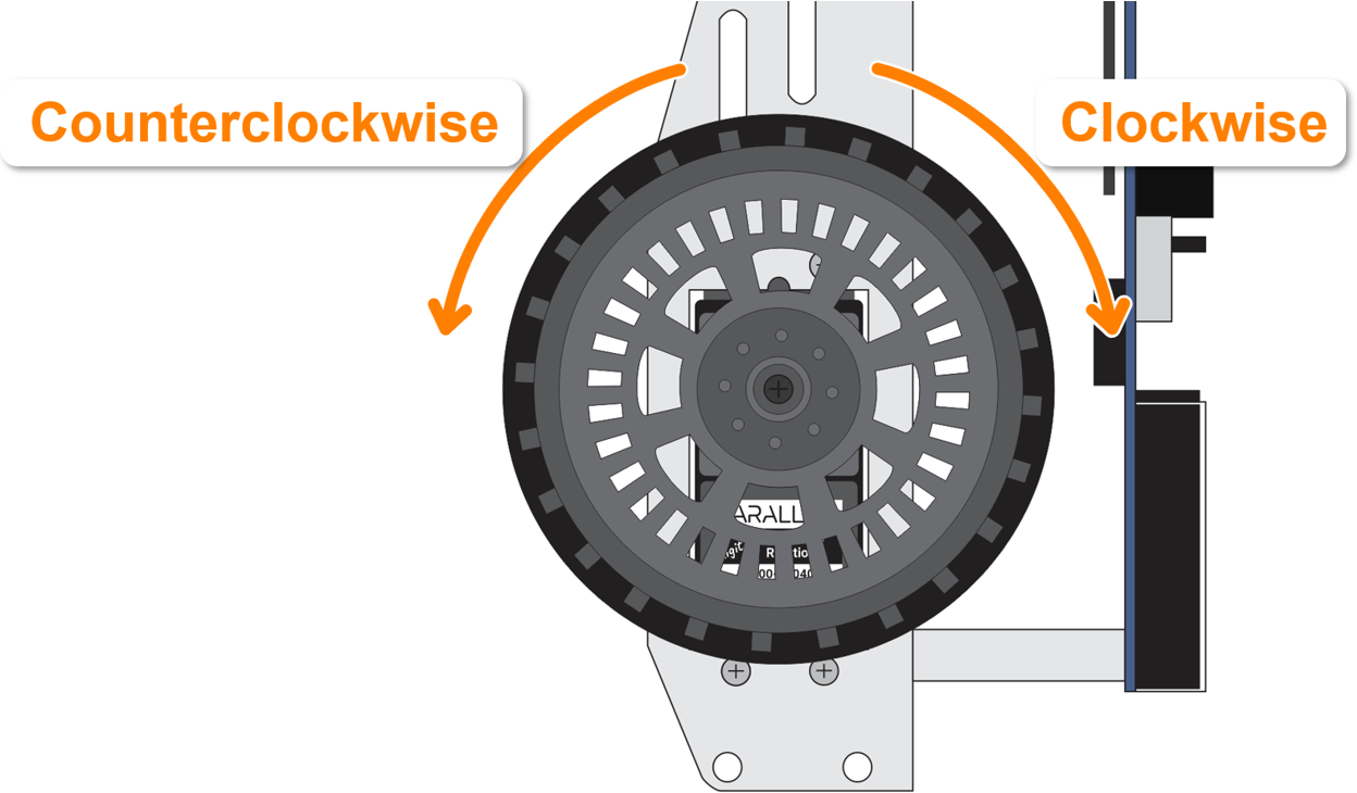
Counterclockwise vs. Clockwise
If the top of the wheel rotates left, it turns counterclockwise. If the top of the wheel rotates right, it turns clockwise.
- Make a note of counterclockwise vs. clockwise since you’ll be checking the direction a servo turns.
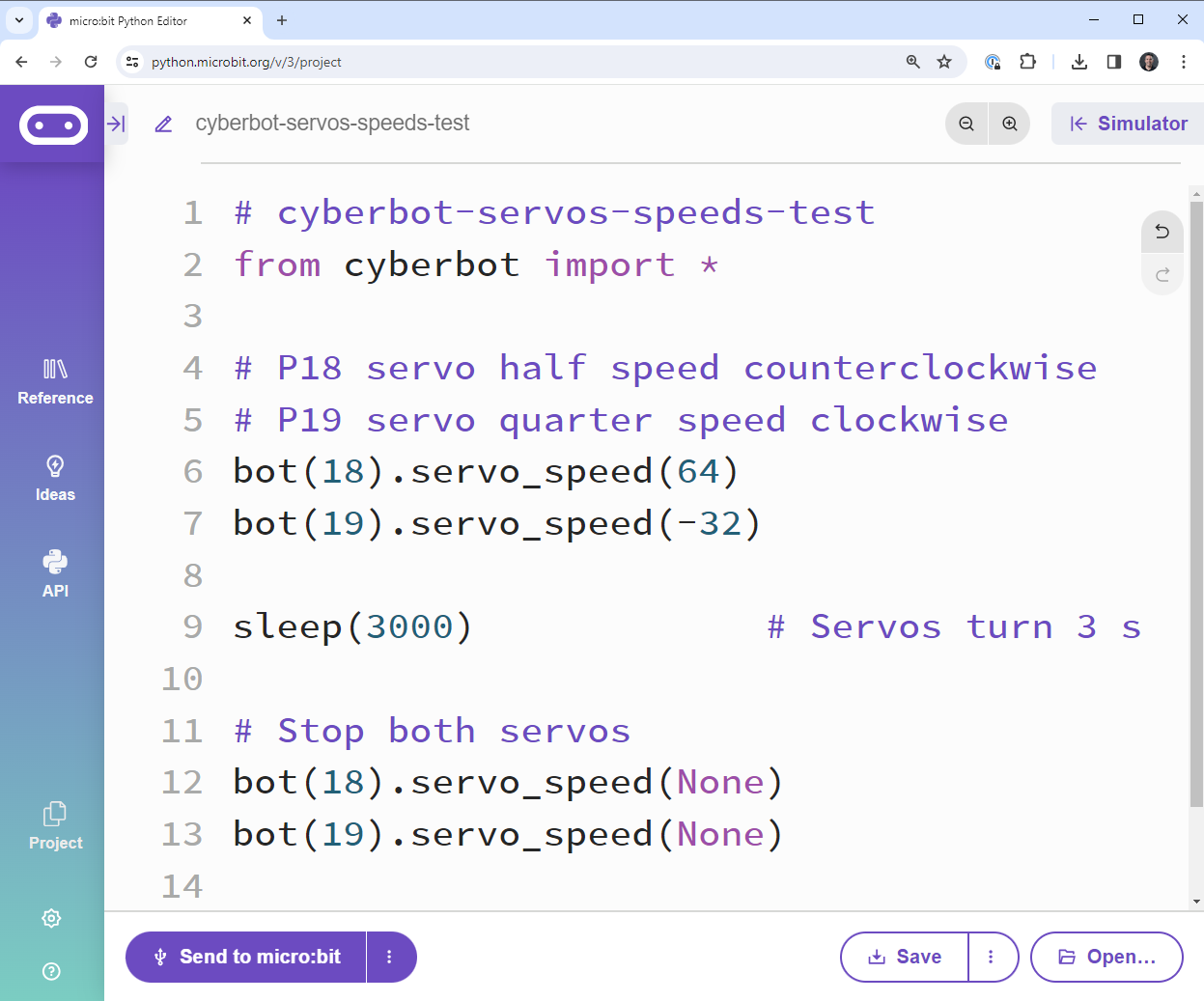
Script: cyberbot-servo-speeds-test
- Right-click cyberbot-template-with-blink and select Save link as…
- In the micro:bit Python Editor, click Open.
- Browse to and open the cyberbot-template-with-blink.hex file you just downloaded.
- Change the script’s name to cyberbot-servos-speeds-test.
- Enter the script as shown below.
- Use the Save button to save the project.
Tests
- Flash the script into the micro:bit with the Send to micro:bit button.
- Set the cyber:bot board’s PWR switch to 2.
- If it took you longer than 3 seconds to set PWR to 2, the script might already be done. Just click the Send to micro:bit button again to re-run the script.

- Monitor the wheel speeds as they turn for three seconds.
- Click Send to micro:bit again as many times as needed as you observe the wheel speeds. Verify the wheel speeds and directions:
- The servo connected to P18 (left servo) should be turning counterclockwise for 3 seconds.
- The servo connected to P19 (right servo) should be turning more slowly, and in the opposite direction (clockwise).
How it Works
The bot(18).servo_speed(64) statement makes the servo turn at about half of its full speed, in the counterclockwise direction. The bot(19).servo_speed(-32) makes the P19 servo turn the opposite direction, and slower than the other servo.
After setting the servo speeds, they will continue indefinitely. The sleep(3000) statement ensures that the servos will keep turning for three seconds.
After 3 seconds, bot(18).servo_speed(None) and bot(19).servo_speed(None) make the servos stop.
In case you’re wondering what the difference is between bot(18).servo_speed(0) and bot(18).servo_speed(None): Using a speed of 0 keeps up the control signal that makes the servo move (or stay still at 0). In contrast, None takes away that signal altogether. We use None to make sure adjustable servos that aren’t precisely centered stay still anyhow.
Your Turn
In bot(pin).servo_speed(velocity), the velocity argument can be anywhere in the -200 to 200 range. For turning counterclockwise, the speed control range is 15 (slow) through 115 (fast). For turning clockwise, the speed control range is -15 (slow) through -115 (fast). Values in the 115 through 200 range (and -115 through -200) are considered overdrive because it’s asking the servos to go faster than they can. The stop range or deadband range is -15 through + 15.
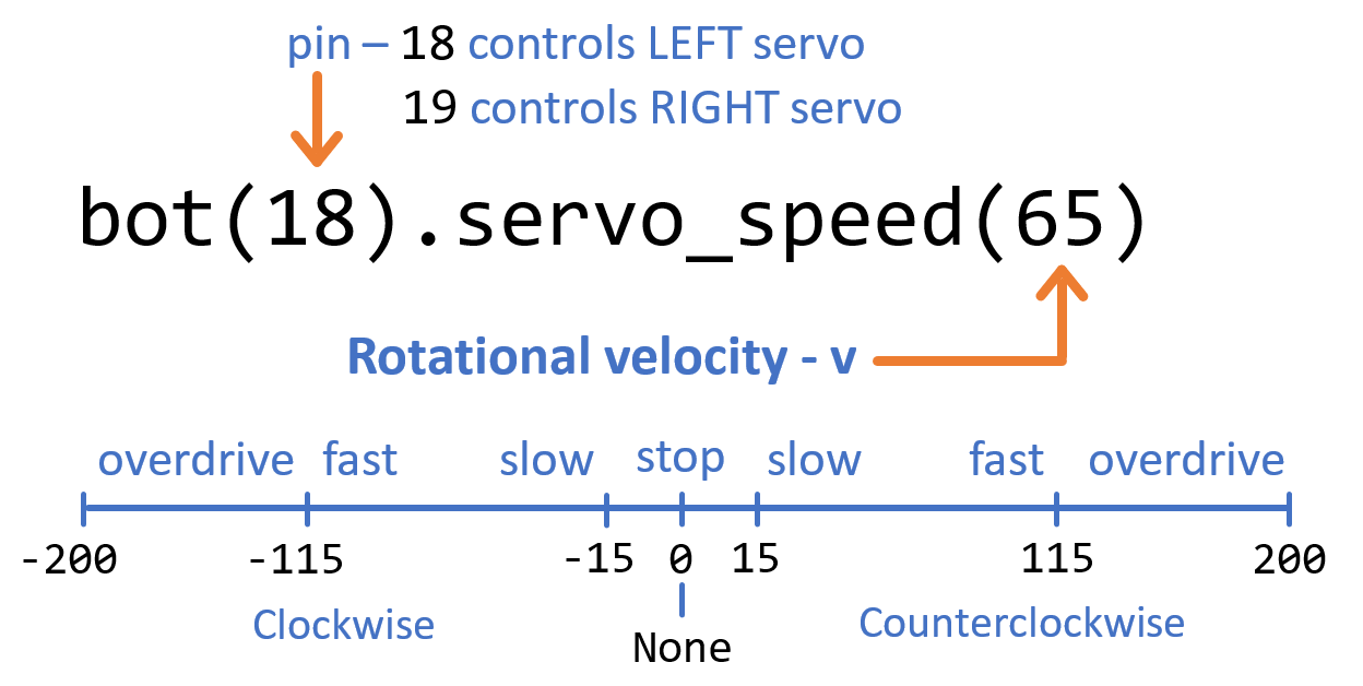
Your servos may differ. The velocity values here are typical values, and servos will vary. As an example, your servo might not start moving until the velocity is set to 20 or 25. Likewise, it might not reach top speed until 135 or even 140. The stop range will also vary, especially for servos that were centered by a screwdriver. For example, one servo might have a stop range of -1 through 19, while another might have a stop range of -9 through 9.
- Take the servo connected to P18 and place a small piece of tape on the edge of its wheel.
- Open cyberbot-servos-speeds-test.
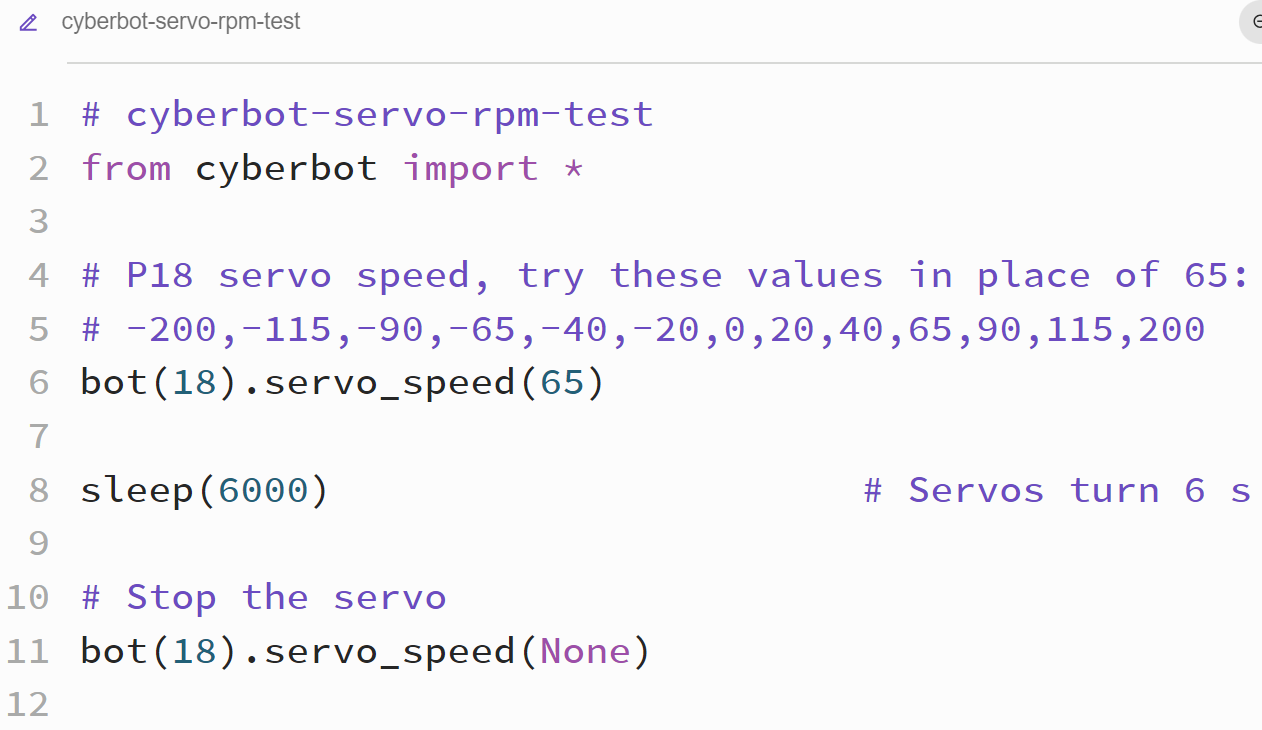
- Name it cyberbot-servos-rpm-test.
- Modify the script to match the script below.
- Save the script.
- Set the PWR switch to 2.
- Flash the script into the micro:bit by clicking the Send to micro:bit button.
- Using the tape as a marker, count the number of times the wheel turns in 6 seconds. Do your best to approximate the factional part, like if it stops ¼ of the way into its 3rd turn, call that 3.25 revolutions.
- Multiply the number of revolutions by 10 for the wheel’s revolutions per minute (RPM) rate.
- Change the velocity value on line 6 from 65 to -200, re-flash the script into the cyber:bot, and repeat the RPM measurement.
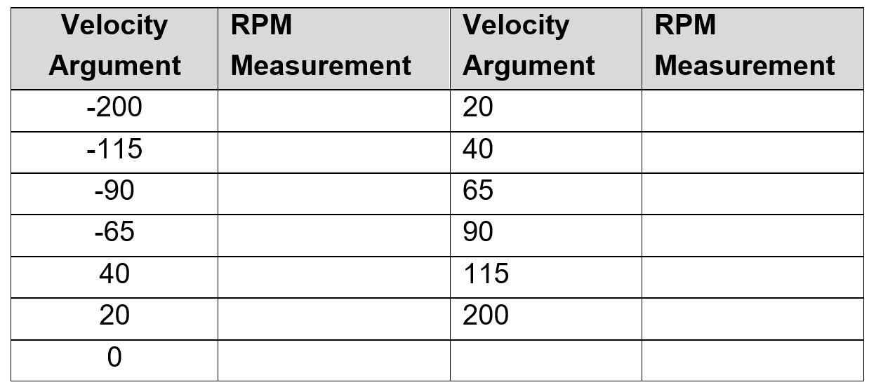
- When the wheel spins clockwise, make the RPM value negative. For example, maybe the -200 test resulted in -50 RPM (clockwise rotation), but the positive 200 velocity value would result in +50 RPM (counterclockwise wheel rotation).
- Record your RPM measurements in this table.
Did You Know – Servo Transfer Function
By taking more measurements like you just did and plotting the RPM as the y-axis and the velocity value from bot(18).servo_speed(velocity) as the x-axis, you’ll have a graph that looks like the one below. The graph is sometimes called a transfer function, as it “transfers” the velocity argument to servo speed and direction. This is a transfer function for a particular servo with the jumper set to 5V. Your servo’s transfer function will differ.
![]()
You can use this graph in two ways. First, you can figure out what velocity argument to use for a desired RPM speed. For this, you would start with a y-axis value, go right to the graphed line and then go down to find the x-axis value, you will know what velocity argument to use for a desired RPM. Example, starting with -25 RPM (clockwise), go right, to the graph, and then go down from there to find that the velocity argument would need to be about 60.
Another way to use this graph would be to predict what speed will come from a given velocity argument. For example, start at the bottom with a velocity value of about 55. Go straight up to the graphed line, then left to see that it results in +25 RPM (counterclockwise).
The servo these tests were run on has a speed of 25 for a velocity argument of 55, but a speed of -25 for a velocity argument of -60. These differences are typical for continuous rotation servos, and you might find later, that you’ll need velocity values that are not identical to make your robot go straight ahead (like 55 and 60 to match the wheel speeds in opposite directions). Since the graph is not a perfect mirror image, it is referred to as asymmetrical.
Did You Know – Servo Control Signals
The graphs below are of the signals the cyber:bot board sends through the white wires to control the servos. These graphs of high/low signals with volts on the y-axis and time on the x-axis are called timing diagrams. If you were to connect LED lights to those top pins on the P18 and P19 servo ports, they would glow dimly in response to the servo control signals. The lights would be flickering too rapidly for the eye to detect. The reason the lights would look dim is because they are off most of the time, and only on for brief periods of time.
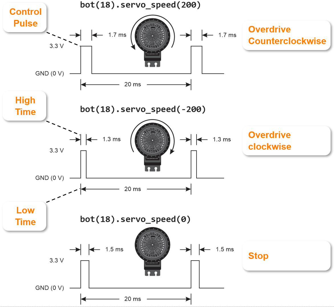
These are graphs of the signals that repeat every 20 ms (50 times per second). This first graph is of a signal that’s overdrive in the counterclockwise direction. Each time the level of the graph is at 3.3 V for 1.7 ms, if a light was connected, it would turn on. These 3.3 V high signals are called control pulses. The GND (0 V) level lasts for 18.3 ms, during which time the light would turn off. These low signals do not have any specific name.
This second graph is of a signal that’s overdrive in the clockwise direction. The control pulses last 1.3 ms, and the low time lasts the remaining 18.7 ms. Halfway between the counterclockwise and clockwise control pulse widths is the stay still signal, with pulse widths of 1.5 ms, and the remaining low times last 18.5 ms.