Build the IR Sensor Circuits
In this activity, you will build and test the infrared object sensor system to make sure they detect objects in front of the ActivityBot. Just like the whisker circuits, there is one on the right and one on the left so the ActivityBot can determine which way to turn in relation to the obstacle.
In this case, each side needs two electronic components: an LED that rapidly flashes infrared light, and an infrared receiver to detect a reflection of that infrared light bouncing off of objects nearby.
Circuit
Parts Required
(2) IR LEDs
(2) IR receivers
(2) 1 k-ohm resistors (brown-black-red)
(2) 220-ohm resistors (red-red-brown)
Assemble the IR Headlights
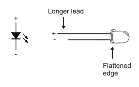
The infrared LEDs are designed to sit in the standoff tubes a certain way. The flat spot on the LED dome matches a flat ledge inside the tube. Holes on the bottom of the tube are labeled for the anode (+) and cathode (-) leads.
- Find the two IR LEDs in your kit — they are the clear ones with dome-shaped (not flat) tops.
- Insert the infrared LED into the LED standoff tube, threading the anode and cathode leads through their respective holes in the bottom. If properly aligned, the LED should drop in place without pushing.
- Slip the short tube over the IR LED’s clear plastic case, tab end first. The tabs should snap into the standoff, holding the LED in place.
To direct the IR LED’s light, just like a flashlight beam, we’ll use an IR LED standoff (longer tube) and shield (shorter tube). The style of the standoff and light shield may vary, but they still fit together the same way.
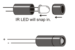
- Insert the IR LED’s leads into the standoff tube, and out through the two holes at the bottom of the standoff.
- Press firmly and the IR LED should snap into place. If it doesn’t, pull it out, give it a half turn, and try again.
- Fit the LED shield onto the standoff.
Introducing the IR Receiver
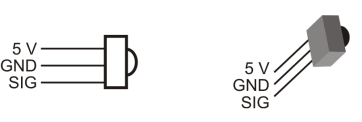
- Find the IR receivers in your kit. The receivers are a small box with three pins and a dome on one side.
- Take a look at the image below and identify the receiver’s 5V, Ground, and Signal pins.
Build the Sensors
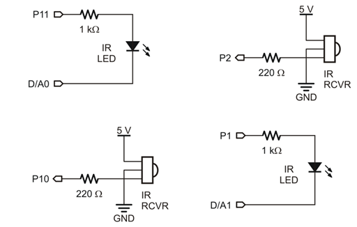
The IR LED’s cathodes are connected to the D/A0 and D/A1 sockets on the Activity Board WX. These two special sockets can output a variable voltage. This voltage can be increased to make the IR LEDs dimmer, for closer range detection. (They can even be tested at different voltages—levels of dimness—to get a rough idea of the object’s distance, but that’s for another activity…)
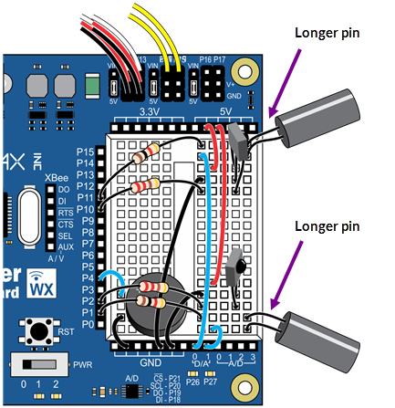
- Use this wiring diagram and schematic to build the infrared detectors.
- Make sure the longer IR LED anode pins — the longer pins— are plugged into the rows shown in the wiring diagram.