Inside the Whisker Circuit (Optional)
Let’s take a look at the right whisker and see what happens when it is not pressed, and then pressed.
When it’s not pressed the whisker does not touch the 3-pin header on the breadboard, so there is no electrical contact between the two. Because of that, the 10 kΩ resistor that’s connected to the 3.3 V socket above the breadboard applies 3.3 V to the breadboard row with the 3-pin header post. The 220 Ω resistor that connects that row to P8 applies the 3.3 V to P8.
The whisker is like a normally open switch. In the schematic, P8 detects 3.3 V through the 220 Ω and 10 kΩ resistors. Whenever a circuit applies 3.3 V (or anything over 1.65 V) to P8, input(8) returns 1. That’s why wR = input(8) copied the value of 1 to the wR variable (and you saw it displayed in the SimpleIDE Terminal).
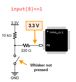
Why 3.3 V at P8? In case you’re wondering why the voltage at P8 is the same as the voltage above the 10 kΩ resistor, here’s what’s going on:
First of all, the schematic shows an open switch with the “Not pressed” label. That open switch is the whisker, which is not in contact with the 3-pin header, and it keeps ground (GND = 0 V) out of the circuit. So, all we have is 3.3 V on one end of a pair of resistors, and P8 on the other end. Since P8 is set to input, it looks invisible to the circuit. As far as the circuit’s concerned, the right side of that 220 Ω resistor might as well be disconnected from everything and sticking up in the air. When only one voltage is applied to a resistor, or even a chain of resistors, that same voltage will appear at the other end as well. So, P8 as an input is invisible to the circuit, but it can detect the voltage the circuit applies to it. In this case, that voltage is 3.3 V, which causes the Propeller to store 1 in its P8 input register, and so input(8) returns the value 1.
When the right whisker is pressed because the robot has bumped into an obstacle, then the right whisker makes contact with the front post on the 3-pin header. The whisker is electrically connected to that plated hole on the corner of the board, which eventually makes its way to the battery’s negative terminal. That negative terminal is commonly called ground, and has a value of 0 V. Since the whisker touches that 3-pin header post, it connects that row to ground, so P8 sees 0 V through the 220 Ω resistor.
Take a look at this schematic. It shows how the whisker connects that node where the 10 kΩ and 220 Ω resistors meet to ground (0 V). …and that’s what P8 detects. As a result, a call to input(8) returns zero. That zero value gets copied to wR with wR = input(8), and that’s what gets displayed by the Parallax Terminal Window when the whisker is pressed.
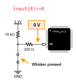
Why 0 V at P8? Now that the whisker is pressed, the schematic above shows 0 V applied to P8. That’s because pushing the whisker up against the post connects GND (0 V) to the node where the 10 kΩ and 220 Ω resistors meet. Now, instead of 3.3 V, the circuit applies 0 V to P8. Reason being, 0 V is being applied to the left side of the 220 Ω resistor, and the circuit still thinks the right side of that resistor is floating in the air. So, the rule for a high impedance input still applies, and the voltage that’s on the right side of the 220 Ω resistor will be the same as the voltage applied to its left side.
Now that there’s 3.3 V on one end of the the 10 kΩ resistor and 0 V on the other end, it applies electrical pressure that causes current to flow through that resistor. You can use the Ohm’s Law equation of V = I x R to figure it out. This equation says the voltage (V) difference at two ends of a resistor is equal to the current (I) pasing through it multiplied by the resistor’s resistance (R). With a little algebra, we have I = V ÷ R = 3.3 V ÷ 10,000 Ω ≈ 0.00033 A. That’s 0.00033 A, or in terms of milliamps, 0.33 mA, a very small amount of current, especially compared about 140 mA, which is what the servos need to make the Propeller ActivityBot move.
The 10 kΩ resistor is called a pull-up resistor. It pulls the voltage at P8 up to 3.3 V when the whisker is not pressed. It’s important to have either a pull-up or pull-down resistors in switch circuits. A pull-up or pull-down resistor applies a voltage that’s opposite of the voltage the I/O pin will detect when the switch/button contact is made. Without it, the I/O pin will allow nearby electric fields to affect whether it reports 1 or 0 to the input function. For example, without that pull-up/pull-down resistor, simply putting your hand near the 220 Ω resistor might change the value the input function reports.