SPI Example
SPI stands for serial peripheral interface, and it’s a communication protocol commonly used for exchanging data between special purpose integrated circuits (ICs) and computing devices (like your Propeller microcontroller). A wide variety of sensor chips use SPI, including ambient temperature sensors, A/D and D/A converters, and the 3-axis accelerometer module in this example.
Some SPI devices will have libraries that support them, with pre-written functions, documentation, and example code to make them easier to use. If the SPI device you need for your project doesn’t have a library, incorporating it into your project will involve reading the device’s datasheet and using that information to write code to make your microcontroller communicate with the device.
This example uses a datasheet to develop test code that communicates with the MMA7455 3-Axis Accelerometer module.
WAIT! What do you want to do?
If you just want to get a quick start using the 3-Axis Accelerometer Module, try the handy mma7455 library in the MMA7455 3-Axis Accelerometer Simple Devices tutorial. If you want to see an example of communicating with an SPI device using shift_out and shift_in functions, keep reading!
Parts
For this activity, we’ll use the MMA7455 3-Axis Accelerometer Module and some jumper wires to connect it to 3.3 V, ground, and Propeller I/O pins.
- (1) MMA7455 3-Axis Accelerometer Module
- (5) Jumper Wires
Circuit
In addition to 3.3 V and GND, this circuit has three connections for SPI communication:
CLK — it’s the clock line, connected to P8 in our example. The Propeller microcontroller sends series of high/low signals on this line, to tell the device it’s time to check for (or send) a data bit on the DATA line. (The CLK line might be labeled SCLK or SCK on other devices.)
DATA — Binary values are sent and received on this line, which is connected to P7 here. Data is sent with each repetition of the CLK line’s signal.
CS — this stands for “chip select” line, which is connected to P6 in this circuit. The microcontroller sets a given device’s CS line low during data exchanges, and takes it high again when done. (You might see this line labeled nCS, CSB, CNS, NSS, STE, or SYNC on other devices.)
Let’s connect the Propeller microcontroller and an SPI device — the MMA7455 3-Axis Accelerometer module — to form an SPI bus so they can communicate.
- Build the circuit shown in the schematic and wiring diagram.
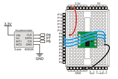
Note from the schematic that the DATA line, connected to P7, is bidirectional. Other SPI chips may need buses with separate data-out and data-in lines. The chip’s documentation might label a data-out line DOUT, DO, or MISO (microcontroller-in-serial-out). Likewise, the chip’s data-in line might be labeled DIN, DI, or MOSI (microcontroller-out-serial-in). A bidirectional line might be labeled DIO.
If you haven’t already installed the latest USB driver, SimpleIDE, or Learn folder, go to Propeller C – Set up SimpleIDE and Propeller C – Start Simple.
Test Code
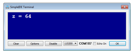
For simplicity, this test code only monitors the accelerometer’s z-axis. Setting the board flat will align the z-axis with the earth’s gravitational field. This gives a measurement of 64, representing 1 g of gravitational pull on the mass inside the accelerometer. Turn the board upside-down, and you’ll get a -64; and setting it on its edge should result in a measurement near zero.
- Click the New Project button, and save it as Test Z Axis.side in …DocumentsSimpleIDEMy Projects.
- Copy the code below and paste into SimpleIDE.
- Click the Run with Terminal button.
- Check the measurements when you: 1) have the board sitting face up on the table, 2) face down, and 3) on its edge.
/*
  MMA7455 Test Z Axis.c
*/

#include "simpletools.h"                          // Include simpletools lib

signed char z;                                    // Z-axis value

int main()                                        // Main function
{
  high(6);                                        // CS line high (inactive)
  low(8);                                         // CLK line low
  low(6);                                         // CS -> low start SPI

  shift_out(7, 8, MSBFIRST, 7, 0b1010110);        // Write MCTL register
  shift_out(7, 8, MSBFIRST, 1, 0b0);              // Send don't-care bit
  shift_out(7, 8, MSBFIRST, 8, 0b01100101);       // Value for MCTL register

  high(6);                                        // CS -> high stop SPI
  pause(1);

  while(1)                                        // Main loop
  {
    low(6);                                       // CS low selects chip
    shift_out(7, 8, MSBFIRST, 7, 0b0001000);      // Send read register address
    shift_out(7, 8, MSBFIRST, 1, 0b0);            // Send don't-care value

    z = shift_in(7, 8, MSBPRE, 8);                // Get value from register

    high(6);                                      // De-select chip
    print("%c z = %d%c", HOME, z, CLREOL);        // Display measurement
    pause(500);                                   // Wait 0.5 s before repeat
  }
}