Skip to content
Parallax Learn

Parallax Learn

  • Welcome
  • Tutorials
        • Tutorial Series head tag

          Tutorial Series
        • Tutorial Series

          The special, classroom-ready series pages are organized collections of tutorials for our most popular hardware and/or languages. The tutorials for each topic are conveniently accessible from a single page, shown in the order it is recommended that they be completed.
        • Robotics Series Head tag

          Robotics Series
        • Robotics Series

          • Artificial Intelligence
          • Cybersecurity: Radio Data tutorialCybersecurity
          • cyber:bot + Python
          • cyber:bot + MakeCode
          • Boe-Bot Tutorial SeriesBoe-Bot
          • Arduino Shield-Bot
          • ActivityBot with C TutorialsActivityBot + C
          • ActivityBot with BlocklyProp Tutorial SeriesActivityBot + BlocklyProp
          • Scribbler 3 Tutorial SeriesScribbler 3
        • Electronics & Programming Series Head tag

          Electronics & Programming Series
          • BS2 Board of Education Tutorial SeriesBS2 Board of Education
          • Propeller C-Language BasicsPropeller C Basics
          • FLiP Try-It Kit C Tutorial SeriesFLiP Try-It Kit + C
          • FLiP Try-It Kit BlocklyProp TutorialsFLiP Try-It Kit + BlocklyProp
          • Badge WX Tutorial SeriesBadge WX
          • Propeller BlocklyProp Basics and ProjectsPropeller BlocklyProp Basics
          • View All Tutorial Series »
        • Browse Tutorials
        • Browse Tutorials

          Individual tutorials sorted by robot or kit, and language.
        • By Robot or Kit
          • ActivityBot
          • SumoBot WX
          • Boe-Bot
          • Shield-Bot
          • cyber:bot
          • Badge WX
          • ELEV-8
          • ARLO
        • By Language
        • By Language

          • Propeller C
          • Arduino
          • BlocklyProp
          • PBASIC
          • Python
          • MakeCode
          • View All Tutorials »
  • Educators
  • Reference
  • Downloads
  • Home
  • All Courses
  • QTI Line Following ActivityBot with BlocklyProp

QTI Line Following ActivityBot with BlocklyProp

Test the QTI Sensors

Now it is time to test the QTI sensors. 

  • In BlocklyProp Solo, make a new project for your board.
  • Build the block of code shown below. It fetches the output state of each sensor with a “QTIs” function, then displays the results in the Terminal.

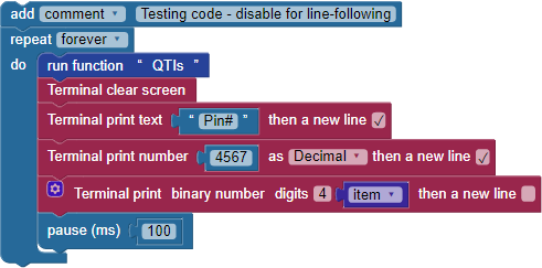
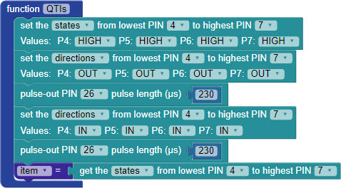
  • Then, build the QTIs function shown below.  (This function will also be used for line-following later.)

The white paper will reflect infrared light, while the black line will absorb it. Each QTI sensor emits infrared light, then looks for a reflection.  When a QTI sensor is over a black line, it will return a “1” and when it is over a white surface, it will return a “0.”

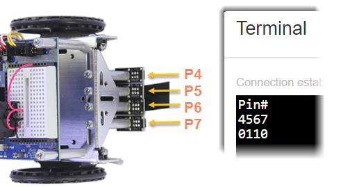
  • Position your robot over the black line on your track.  The QTI sensors directly over the line should return a 1, and those over a white area should return a 0.
  • Move the robot around slightly to test each QTI sensor.
  • If the sensors don’t see the line, try the following adjustments: 
    • Double-check all of your wiring connections to make sure the sensors are properly connected to power, ground, and each I/O pin.
    • Try replacing the jumper wire connecting to 5 V with a 220 ohm resistor. This makes the QTIs less bright, which might be overwhelming with a shiny line or shiny paper.
    • Try removing the Nylon spacers from one of the sensor’s posts. If this improves performance, remove it from the rest of the posts.

How the QTIs Function Works

The QTIs function starts by setting the I/O pin states for all four QTI sensors to HIGH, with the direction OUT.  This causes each QTI sensor to turn on its infrared LED. The pulse-out PIN 26 pulse length µs 230 block keeps the LEDs on for just a  230 microsecond flash. (We could not use the pause block here, because its shortest duration is 1 millisecond, which is 1000 microseconds). 

After that, the I/O pin directions are set to IN (input) for another 230 microseconds.  Each QTI sensor is looking for its infrared flash’s reflection, and reports I/O pin as a zero if the reflection is seen and a 1 if it is not. 

Then, the states of the four I/O pins are saved in the item variable as a four-digit binary number. So, each time through the drive routine’s loop, the QTIs function updates the item variable before it gets used for navigation with the switch…case block.


Printer-friendly version
Build the QTI Line Follower
Prev
Program for Line-Following
Next

DISCUSSION FORUMS | PARALLAX INC. STORE

About | Terms of Use | Feedback: learn@parallax.com | Copyright©Parallax Inc. 2024

© 2025 Parallax Learn • Built with GeneratePress