Skip to content
Parallax Learn

Parallax Learn

  • Welcome
  • Tutorials
        • Tutorial Series head tag

          Tutorial Series
        • Tutorial Series

          The special, classroom-ready series pages are organized collections of tutorials for our most popular hardware and/or languages. The tutorials for each topic are conveniently accessible from a single page, shown in the order it is recommended that they be completed.
        • Robotics Series Head tag

          Robotics Series
        • Robotics Series

          • Artificial Intelligence
          • Cybersecurity: Radio Data tutorialCybersecurity
          • cyber:bot + Python
          • cyber:bot + MakeCode
          • Boe-Bot Tutorial SeriesBoe-Bot
          • Arduino Shield-Bot
          • ActivityBot with C TutorialsActivityBot + C
          • ActivityBot with BlocklyProp Tutorial SeriesActivityBot + BlocklyProp
          • Scribbler 3 Tutorial SeriesScribbler 3
        • Electronics & Programming Series Head tag

          Electronics & Programming Series
          • BS2 Board of Education Tutorial SeriesBS2 Board of Education
          • Propeller C-Language BasicsPropeller C Basics
          • FLiP Try-It Kit C Tutorial SeriesFLiP Try-It Kit + C
          • FLiP Try-It Kit BlocklyProp TutorialsFLiP Try-It Kit + BlocklyProp
          • Badge WX Tutorial SeriesBadge WX
          • Propeller BlocklyProp Basics and ProjectsPropeller BlocklyProp Basics
          • View All Tutorial Series »
        • Browse Tutorials
        • Browse Tutorials

          Individual tutorials sorted by robot or kit, and language.
        • By Robot or Kit
          • ActivityBot
          • SumoBot WX
          • Boe-Bot
          • Shield-Bot
          • cyber:bot
          • Badge WX
          • ELEV-8
          • ARLO
        • By Language
        • By Language

          • Propeller C
          • Arduino
          • BlocklyProp
          • PBASIC
          • Python
          • MakeCode
          • View All Tutorials »
  • Educators
  • Reference
  • Downloads
  • Home
  • All Courses
  • Robotics with the Board of Education Shield for Arduino

Robotics with the Board of Education Shield for Arduino

Introducing the Prototyping Area

The white board with lots of square sockets in it is called a solderless breadboard.  This breadboard has 17 rows of sockets. In each row, there are two five-socket groups separated by a trench in the middle. All the sockets in a 5-socket group are connected together underneath with a conductive metal clip. So, two wires plugged into the same 5‑socket group make electrical contact. This is how you will connect components, such as an LED and resistor, to build circuits. Two wires in the same row on opposite sides of the center trench will not be connected. 

The prototyping area also has black sockets along the top, bottom, and left. 

  • Top: these sockets have three supply voltages for the breadboard: 3.3 V, Vin (input voltage from either battery pack or programming cable), and 5 V. 
  • Bottom-left: The first six sockets along the bottom-left are ground terminals, labeled GND; think of them as a supply voltage that’s 0 V.  Collectively, the 3.3V, Vin, 5V and GND are called the power terminals, and they will be used to supply your circuits with electricity. 
  • Bottom-right: The ANALOG IN sockets along the bottom-right are for measuring variable voltages; these connect to the Arduino module’s ANALOG IN sockets.
  • Left: The DIGITAL sockets on the left have labels from 0 to 13.  You will use these to connect your circuit to the Arduino module’s digital input/output pins.

Digital and analog pins are the small pins on the Arduino module’s Atmel microcontroller chip.  These pins electrically connect the microcontroller brain to the board.
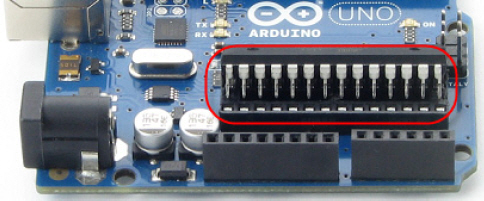
A sketch can make the digital pins send high or low signals to circuits. In this chapter, we’ll do that to turn lights on and off. A sketch can also make a digital pin monitor high or low signals coming from a circuit; We’ll do that in another chapter to detect whether a contact switch has been pressed or released.

A sketch can also measure the voltages applied to analog pins; we’ll do that to measure light with a phototransistor circuit in another chapter.

How To: The Basics of Breadboarding (A YouTube video from Parallax Inc.)

Printer-friendly version
Introducing the LED
Prev
LED Test Circuit
Next

DISCUSSION FORUMS | PARALLAX INC. STORE

About | Terms of Use | Feedback: learn@parallax.com | Copyright©Parallax Inc. 2024

© 2025 Parallax Learn • Built with GeneratePress