Skip to content
Parallax Learn

Parallax Learn

  • Welcome
  • Tutorials
        • Tutorial Series head tag

          Tutorial Series
        • Tutorial Series

          The special, classroom-ready series pages are organized collections of tutorials for our most popular hardware and/or languages. The tutorials for each topic are conveniently accessible from a single page, shown in the order it is recommended that they be completed.
        • Robotics Series Head tag

          Robotics Series
        • Robotics Series

          • Artificial Intelligence
          • Cybersecurity: Radio Data tutorialCybersecurity
          • cyber:bot + Python
          • cyber:bot + MakeCode
          • Boe-Bot Tutorial SeriesBoe-Bot
          • Arduino Shield-Bot
          • ActivityBot with C TutorialsActivityBot + C
          • ActivityBot with BlocklyProp Tutorial SeriesActivityBot + BlocklyProp
          • Scribbler 3 Tutorial SeriesScribbler 3
        • Electronics & Programming Series Head tag

          Electronics & Programming Series
          • BS2 Board of Education Tutorial SeriesBS2 Board of Education
          • Propeller C-Language BasicsPropeller C Basics
          • FLiP Try-It Kit C Tutorial SeriesFLiP Try-It Kit + C
          • FLiP Try-It Kit BlocklyProp TutorialsFLiP Try-It Kit + BlocklyProp
          • Badge WX Tutorial SeriesBadge WX
          • Propeller BlocklyProp Basics and ProjectsPropeller BlocklyProp Basics
          • View All Tutorial Series »
        • Browse Tutorials
        • Browse Tutorials

          Individual tutorials sorted by robot or kit, and language.
        • By Robot or Kit
          • ActivityBot
          • SumoBot WX
          • Boe-Bot
          • Shield-Bot
          • cyber:bot
          • Badge WX
          • ELEV-8
          • ARLO
        • By Language
        • By Language

          • Propeller C
          • Arduino
          • BlocklyProp
          • PBASIC
          • Python
          • MakeCode
          • View All Tutorials »
  • Educators
  • Reference
  • Downloads
  • Home
  • All Courses

Robotics with the Board of Education Shield for Arduino

Curriculum

  • 9 Sections
  • 148 Lessons
  • Lifetime
Expand all sectionsCollapse all sections
  • About This Tutorial
    3
    • 2.0
      About the BOE Shield-Bot
    • 2.1
      Audience and Support
    • 2.2
      Author & Contributors
  • Chapter 1. Your Shield-Bot's Brain
    25
    • 3.1
      Chapter 1. Your Shield-Bot’s Brain
    • 3.2
      Hardware and Software Options
    • 3.3
      Shield-Bot Chassis Parts
    • 3.4
      Shield-Bot Hardware
    • 3.5
      Shield-Bot Electronics Parts
    • 3.6
      Activity 1: Download and Install the Software
    • 3.7
      Activity 2: Write a Simple “Hello!” Sketch
    • 3.8
      Codebender Hello Sketch
    • 3.9
      How the Hello Sketch Code Works
    • 3.10
      Modify the Sketch to Repeat
    • 3.11
      Hello Messages on New Lines
    • 3.12
      Open the Arduino Reference
    • 3.13
      Activity 3: Store and Retrieve Values
    • 3.14
      Global vs.Local Variables
    • 3.15
      Activity 4: Solve Math Problems
    • 3.16
      Try Floating Point Math
    • 3.17
      Activity 5: Make Decisions
    • 3.18
      More Decisions with if… else if
    • 3.19
      Activity 6: Count and Control Repetitions
    • 3.20
      How the for Loop Works
    • 3.21
      Adjust Initialization, Condition, and Increment
    • 3.22
      Activity 7: Constants and Comments
    • 3.23
      Chapter 1 Summary
    • 3.24
      Chapter 1 Challenges
    • 3.25
      Chapter 1 Solutions
  • Chapter 2. Shield, Lights, Servo Motors
    23
    • 4.0
      Chapter 2. Shield, Lights, Servo Motors
    • 4.1
      Activity 1: Board of Education Shield Setup
    • 4.2
      Activity 2: Build and Test LED Indicator Lights
    • 4.3
      Introducing the Resistor
    • 4.4
      Introducing the LED
    • 4.5
      Introducing the Prototyping Area
    • 4.6
      LED Test Circuit
    • 4.7
      How a Sketch Makes the LED Turn On and Off
    • 4.8
      Introducing the Timing Diagram
    • 4.9
      Activity 3: LED Servo Signal Monitors
    • 4.10
      How to Use the Arduino Servo Library
    • 4.11
      Activity 4: Connect Servo Motors and Batteries
    • 4.12
      Connect the Servos to the BOE Shield
    • 4.13
      Connect the Battery Pack to the BOE Shield
    • 4.14
      5-cell Pack Setup
    • 4.15
      4-cell Pack + Boe-Boost Setup
    • 4.16
      Activity 5: Centering the Servos
    • 4.17
      Activity 6: Testing the Servos
    • 4.18
      Controlling Servo Speed and Direction
    • 4.19
      How To Control Servo Run Time
    • 4.20
      Chapter 2 Summary
    • 4.21
      Chapter 2 Challenges
    • 4.22
      Chapter 2 Solutions
  • Chapter 3. Assemble and Test your BOE Shield-Bot
    22
    • 5.0
      Chapter 3. Assemble and Test your BOE Shield-Bot
    • 5.1
      Activity 1: Assembling the BOE-Shield-Bot
    • 5.2
      Mount the Topside Hardware
    • 5.3
      Remove the Servo Horns
    • 5.4
      Mount the Servos on the Chassis
    • 5.5
      Mount the Battery Pack
    • 5.6
      Mount the Wheels
    • 5.7
      Attach the BOE Shield to the Chassis
    • 5.8
      Activity 2: Re-test the Servos
    • 5.9
      Testing the Left and Right Wheels
    • 5.10
      Servo Troubleshooting
    • 5.11
      Activity 3: Start-Reset Indicator
    • 5.12
      Build the Piezospeaker Circuit
    • 5.13
      Programming the Start-Reset Indicator
    • 5.14
      Example Sketch: StartResetIndicator
    • 5.15
      Activity 4: Test Speed Control
    • 5.16
      Example Sketch: Test Servo Speed
    • 5.17
      How TestServoSpeed Works
    • 5.18
      Optional: Record Your Own Transfer Curve Data
    • 5.19
      Chapter 3 Summary
    • 5.20
      Chapter 3 Challenges
    • 5.21
      Chapter 3 Solutions
  • Chapter 4. BOE Shield-Bot Navigation
    19
    • 6.0
      Chapter 4. BOE Shield-Bot Navigation
    • 6.1
      Activity 1: Basic BOE Shield-Bot Maneuvers
    • 6.2
      How ForwardThreeSeconds Works
    • 6.3
      Moving Backward, Rotating, and Pivoting
    • 6.4
      Activity 2: Tuning the Basic Maneuvers
    • 6.5
      Tuning the Turns
    • 6.6
      Activity 3: Calculating Distances
    • 6.7
      Activity 4: Ramping Maneuvers
    • 6.8
      Activity 5: Simplify Navigation with Functions
    • 6.9
      Function Call with Parameters
    • 6.10
      Put Maneuvers Into Functions
    • 6.11
      Activity 6: Custom Maneuver Function
    • 6.12
      Activity 7: Maneuver Sequences with Arrays
    • 6.13
      Using Array Elements
    • 6.14
      Navigation with Arrays
    • 6.15
      Character Arrays and switch-case
    • 6.16
      Chapter 4 Summary
    • 6.17
      Chapter 4 Challenges
    • 6.18
      Chapter 4 Solutions
  • Chapter 5. Tactile Navigation with Whiskers
    13
    • 7.0
      Chapter 5. Tactile Navigation with Whiskers
    • 7.1
      Activity 1: Build and Test the Whiskers
    • 7.2
      How Whisker Switches Work
    • 7.3
      Testing the Whiskers
    • 7.4
      How DisplayWhiskerStates Works
    • 7.5
      Activity 2: Field-Test the Whiskers
    • 7.6
      Activity 3: Navigation with Whiskers
    • 7.7
      How RoamingWithWhiskers Works
    • 7.8
      Activity 4: Artificial Intelligence for Escaping Corners
    • 7.9
      How Escaping Corners Works
    • 7.10
      Chapter 5 Summary
    • 7.11
      Chapter 5 Challenges
    • 7.12
      Chapter 5 Solutions
  • Chapter 6. Light-Sensitive Navigation with Phototransistors
    18
    • 8.0
      Chapter 6. Light-Sensitive Navigation with Phototransistors
    • 8.1
      Introducing the Phototransistor
    • 8.2
      Activity 1: Simple Light to Voltage Sensor
    • 8.3
      Example Sketch: PhototransistorVoltage
    • 8.4
      Halt Under the Bright Light
    • 8.5
      How the Phototransistor Circuit Works
    • 8.6
      Ohm’s Law
    • 8.7
      Activity 2: Measure Light Levels Over a Larger Range
    • 8.8
      Building the Photosensitive Eyes
    • 8.9
      Test the Phototransistor Circuit
    • 8.10
      rcTime and Voltage Decay
    • 8.11
      Activity 3: Light Measurements for Roaming
    • 8.12
      Light Measurement Graphic Display
    • 8.13
      Activity 4: Test a Light-Roaming Routine
    • 8.14
      Activity 5: Shield-Bot Navigating by Light
    • 8.15
      Chapter 6 Summary
    • 8.16
      Chapter 6 Challenges
    • 8.17
      Chapter 6 Solutions
  • Chapter 7. Navigating with Infrared Headlights
    14
    • 9.0
      Chapter 7. Navigating with Infrared Headlights
    • 9.1
      Infrared Light Signals
    • 9.2
      Activity 1: Build and Test the Object Detectors
    • 9.3
      Object Detection Test Code
    • 9.4
      Activity 2: Field Testing
    • 9.5
      Sniffing for IR Interference
    • 9.6
      Activty 3: Detection Range Adjustments
    • 9.7
      Activity 4: Object Detection and Avoidance
    • 9.8
      Activity 5: High-performance IR Navigation
    • 9.9
      Activity 6: Drop-off Detector
    • 9.10
      Example Sketch: AvoidTableEdge
    • 9.11
      Chapter 7 Summary
    • 9.12
      Chapter 7 Challenges
    • 9.13
      Chapter 7 Solutions
  • Chapter 8. Robot Control with Distance Detection
    11
    • 10.0
      Chapter 8. Robot Control with Distance Detection
    • 10.1
      Activity 1: Testing the Frequency Sweep
    • 10.2
      Displaying Both Distances
    • 10.3
      Activity 2: BOE Shield-Bot Shadow Vehicle
    • 10.4
      A Look Inside Proportional Control
    • 10.5
      Example Sketch: FollowingShieldBot
    • 10.6
      Follow the Leader
    • 10.7
      Activity 3: What’s Next?
    • 10.8
      Chapter 8 Summary
    • 10.9
      Chapter 8 Challenges
    • 10.10
      Chapter 8 Solutions

Light Measurement Graphic Display

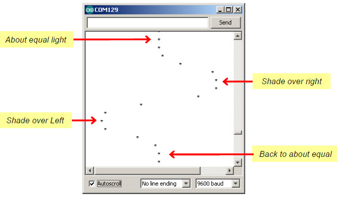
The Serial Monitor screencapture below shows an example of a graphical display of the ndShade variable.  The asterisk will be in the center of the -0.5 to +0.5 scale if the light or shade is the same over both sensors.  If the shade is darker over the BOE Shield-Bot’s right sensor, the asterisk will position to the right in the scale.  If it’s darker over the left, the asterisk will position toward the left.  A larger shade/light contrast (like darker shade over one of the sensors) will result in the asterisk positioning further from the center.

  • Load the LightSensorDisplay sketch into the Arduino.
  • Try casting different levels of shade over each light sensor, and watch how the asterisk in the Serial Monitor responds.  Remember that if you cast equal shade over both sensors, the asterisk should still be in the middle; it only indicates which sensor sees more shade if there’s a difference between them.
/*
 * Robotics with the BOE Shield - LightSensorDisplay
 * Displays a scrolling graph of ndShade.  The asterisk positions ranges
 * from 0 to 40 with 20 (middle of the display) indicating same light on
 * both sides.
 */

void setup()                                 // Built-in initialization block
{
  tone(4, 3000, 1000);                       // Play tone for 1 second
  delay(1000);                               // Delay to finish tone

  Serial.begin(9600);                        // Set data rate to 9600 bps
}  
 
void loop()                                  // Main loop auto-repeats
{
  float tLeft = float(rcTime(8));            // Get left light & make float
  float tRight = float(rcTime(6));           // Get right light & make float
 
  float ndShade;                             // Normalized differential shade
  ndShade = tRight / (tLeft+tRight) - 0.5;   // Calculate it and subtract 0.5
 
  for(int i = 0; i<(ndShade * 40) + 20; i++) // Place asterisk in 0 to 40
  {
    Serial.print(' ');                       // Pad (ndShade * 40) + 20 spaces
  }
  Serial.println('*');                       // Print asterisk and newline

  delay(100);                                // 0.1 second delay
}

long rcTime(int pin)                         // rcTime measures decay at pin
{
  pinMode(pin, OUTPUT);                      // Charge capacitor
  digitalWrite(pin, HIGH);                   // ..by setting pin ouput-high
  delay(5);                                  // ..for 5 ms
  pinMode(pin, INPUT);                       // Set pin to input
  digitalWrite(pin, LOW);                    // ..with no pullup
  long time  = micros();                     // Mark the time
  while(digitalRead(pin));                   // Wait for voltage < threshold
  time = micros() - time;                    // Calculate decay time
  return time;                               // Returns decay time
}

How LightSensorDisplay Works

The loop function starts by taking the two rcTime measurements for the left and right light sensors, and stores them in tLeft and tRight.

void loop()                                  // Main loop auto-repeats
{
  float tLeft = float(rcTime(8));            // Get left light & make float
  float tRight = float(rcTime(6));           // Get right light & make float

After declaring ndShade as a floating-point variable, tLeft and tRight are used in an expression to get that zero-justified normalized differential measurement. The result will be between –0.5 and +0.5, and gets stored in ndShade.

  float ndShade;                             // Normalized differential shade
  ndShade = tRight / (tLeft+tRight) - 0.5;   // Calculate it and subtract 0.5

Next, this for loop places the cursor in the right place for printing an asterisk.  Take a close look at the for loop’s condition.  It takes ndShade and multiples it by 40.  It also has to add 20 to the value because if ndShade is –0.5, we want that to print with zero leading spaces.  So (–0.5 × 40) + 20 = 0.  Now, if ndShade is 0, we want it to print 20 spaces over:  (0 × 40) + 20 = 20.  If it’s +0.5 we want it to print 40 spaces over:  (0.5 × 40) + 20 = 40.  Of course, if it’s something in between, like 0.25, we have (0.25 × 40) + 20 = 30.  So, it’ll print half way between center and far right.

  for(int i = 0; i<(ndShade * 40) + 20; i++) // Place asterisk in 0 to 40
  {
    Serial.print(' ');                       // Pad (ndShade * 40) + 20 spaces
  }

After printing the spaces, a single asterisk prints on the line.  Recall that println prints and also adds a newline so that the next time through the loop, the asterisk will display on the next line.

  Serial.println('*');                       // Print asterisk and newline

  delay(100);                                // 0.1 second delay
}


Printer-friendly version
Activity 3: Light Measurements for Roaming
Prev
Activity 4: Test a Light-Roaming Routine
Next

DISCUSSION FORUMS | PARALLAX INC. STORE

About | Terms of Use | Feedback: learn@parallax.com | Copyright©Parallax Inc. 2024

© 2026 Parallax Learn • Built with GeneratePress