Skip to content
Parallax Learn

Parallax Learn

  • Welcome
  • Tutorials
        • Tutorial Series head tag

          Tutorial Series
        • Tutorial Series

          The special, classroom-ready series pages are organized collections of tutorials for our most popular hardware and/or languages. The tutorials for each topic are conveniently accessible from a single page, shown in the order it is recommended that they be completed.
        • Robotics Series Head tag

          Robotics Series
        • Robotics Series

          • Artificial Intelligence
          • Cybersecurity: Radio Data tutorialCybersecurity
          • cyber:bot + Python
          • cyber:bot + MakeCode
          • Boe-Bot Tutorial SeriesBoe-Bot
          • Arduino Shield-Bot
          • ActivityBot with C TutorialsActivityBot + C
          • ActivityBot with BlocklyProp Tutorial SeriesActivityBot + BlocklyProp
          • Scribbler 3 Tutorial SeriesScribbler 3
        • Electronics & Programming Series Head tag

          Electronics & Programming Series
          • BS2 Board of Education Tutorial SeriesBS2 Board of Education
          • Propeller C-Language BasicsPropeller C Basics
          • FLiP Try-It Kit C Tutorial SeriesFLiP Try-It Kit + C
          • FLiP Try-It Kit BlocklyProp TutorialsFLiP Try-It Kit + BlocklyProp
          • Badge WX Tutorial SeriesBadge WX
          • Propeller BlocklyProp Basics and ProjectsPropeller BlocklyProp Basics
          • View All Tutorial Series »
        • Browse Tutorials
        • Browse Tutorials

          Individual tutorials sorted by robot or kit, and language.
        • By Robot or Kit
          • ActivityBot
          • SumoBot WX
          • Boe-Bot
          • Shield-Bot
          • cyber:bot
          • Badge WX
          • ELEV-8
          • ARLO
        • By Language
        • By Language

          • Propeller C
          • Arduino
          • BlocklyProp
          • PBASIC
          • Python
          • MakeCode
          • View All Tutorials »
  • Educators
  • Reference
  • Downloads
  • Home
  • All Courses

Robotics with the Board of Education Shield for Arduino

Curriculum

  • 9 Sections
  • 148 Lessons
  • Lifetime
Expand all sectionsCollapse all sections
  • About This Tutorial
    3
    • 2.0
      About the BOE Shield-Bot
    • 2.1
      Audience and Support
    • 2.2
      Author & Contributors
  • Chapter 1. Your Shield-Bot's Brain
    25
    • 3.1
      Chapter 1. Your Shield-Bot’s Brain
    • 3.2
      Hardware and Software Options
    • 3.3
      Shield-Bot Chassis Parts
    • 3.4
      Shield-Bot Hardware
    • 3.5
      Shield-Bot Electronics Parts
    • 3.6
      Activity 1: Download and Install the Software
    • 3.7
      Activity 2: Write a Simple “Hello!” Sketch
    • 3.8
      Codebender Hello Sketch
    • 3.9
      How the Hello Sketch Code Works
    • 3.10
      Modify the Sketch to Repeat
    • 3.11
      Hello Messages on New Lines
    • 3.12
      Open the Arduino Reference
    • 3.13
      Activity 3: Store and Retrieve Values
    • 3.14
      Global vs.Local Variables
    • 3.15
      Activity 4: Solve Math Problems
    • 3.16
      Try Floating Point Math
    • 3.17
      Activity 5: Make Decisions
    • 3.18
      More Decisions with if… else if
    • 3.19
      Activity 6: Count and Control Repetitions
    • 3.20
      How the for Loop Works
    • 3.21
      Adjust Initialization, Condition, and Increment
    • 3.22
      Activity 7: Constants and Comments
    • 3.23
      Chapter 1 Summary
    • 3.24
      Chapter 1 Challenges
    • 3.25
      Chapter 1 Solutions
  • Chapter 2. Shield, Lights, Servo Motors
    23
    • 4.0
      Chapter 2. Shield, Lights, Servo Motors
    • 4.1
      Activity 1: Board of Education Shield Setup
    • 4.2
      Activity 2: Build and Test LED Indicator Lights
    • 4.3
      Introducing the Resistor
    • 4.4
      Introducing the LED
    • 4.5
      Introducing the Prototyping Area
    • 4.6
      LED Test Circuit
    • 4.7
      How a Sketch Makes the LED Turn On and Off
    • 4.8
      Introducing the Timing Diagram
    • 4.9
      Activity 3: LED Servo Signal Monitors
    • 4.10
      How to Use the Arduino Servo Library
    • 4.11
      Activity 4: Connect Servo Motors and Batteries
    • 4.12
      Connect the Servos to the BOE Shield
    • 4.13
      Connect the Battery Pack to the BOE Shield
    • 4.14
      5-cell Pack Setup
    • 4.15
      4-cell Pack + Boe-Boost Setup
    • 4.16
      Activity 5: Centering the Servos
    • 4.17
      Activity 6: Testing the Servos
    • 4.18
      Controlling Servo Speed and Direction
    • 4.19
      How To Control Servo Run Time
    • 4.20
      Chapter 2 Summary
    • 4.21
      Chapter 2 Challenges
    • 4.22
      Chapter 2 Solutions
  • Chapter 3. Assemble and Test your BOE Shield-Bot
    22
    • 5.0
      Chapter 3. Assemble and Test your BOE Shield-Bot
    • 5.1
      Activity 1: Assembling the BOE-Shield-Bot
    • 5.2
      Mount the Topside Hardware
    • 5.3
      Remove the Servo Horns
    • 5.4
      Mount the Servos on the Chassis
    • 5.5
      Mount the Battery Pack
    • 5.6
      Mount the Wheels
    • 5.7
      Attach the BOE Shield to the Chassis
    • 5.8
      Activity 2: Re-test the Servos
    • 5.9
      Testing the Left and Right Wheels
    • 5.10
      Servo Troubleshooting
    • 5.11
      Activity 3: Start-Reset Indicator
    • 5.12
      Build the Piezospeaker Circuit
    • 5.13
      Programming the Start-Reset Indicator
    • 5.14
      Example Sketch: StartResetIndicator
    • 5.15
      Activity 4: Test Speed Control
    • 5.16
      Example Sketch: Test Servo Speed
    • 5.17
      How TestServoSpeed Works
    • 5.18
      Optional: Record Your Own Transfer Curve Data
    • 5.19
      Chapter 3 Summary
    • 5.20
      Chapter 3 Challenges
    • 5.21
      Chapter 3 Solutions
  • Chapter 4. BOE Shield-Bot Navigation
    19
    • 6.0
      Chapter 4. BOE Shield-Bot Navigation
    • 6.1
      Activity 1: Basic BOE Shield-Bot Maneuvers
    • 6.2
      How ForwardThreeSeconds Works
    • 6.3
      Moving Backward, Rotating, and Pivoting
    • 6.4
      Activity 2: Tuning the Basic Maneuvers
    • 6.5
      Tuning the Turns
    • 6.6
      Activity 3: Calculating Distances
    • 6.7
      Activity 4: Ramping Maneuvers
    • 6.8
      Activity 5: Simplify Navigation with Functions
    • 6.9
      Function Call with Parameters
    • 6.10
      Put Maneuvers Into Functions
    • 6.11
      Activity 6: Custom Maneuver Function
    • 6.12
      Activity 7: Maneuver Sequences with Arrays
    • 6.13
      Using Array Elements
    • 6.14
      Navigation with Arrays
    • 6.15
      Character Arrays and switch-case
    • 6.16
      Chapter 4 Summary
    • 6.17
      Chapter 4 Challenges
    • 6.18
      Chapter 4 Solutions
  • Chapter 5. Tactile Navigation with Whiskers
    13
    • 7.0
      Chapter 5. Tactile Navigation with Whiskers
    • 7.1
      Activity 1: Build and Test the Whiskers
    • 7.2
      How Whisker Switches Work
    • 7.3
      Testing the Whiskers
    • 7.4
      How DisplayWhiskerStates Works
    • 7.5
      Activity 2: Field-Test the Whiskers
    • 7.6
      Activity 3: Navigation with Whiskers
    • 7.7
      How RoamingWithWhiskers Works
    • 7.8
      Activity 4: Artificial Intelligence for Escaping Corners
    • 7.9
      How Escaping Corners Works
    • 7.10
      Chapter 5 Summary
    • 7.11
      Chapter 5 Challenges
    • 7.12
      Chapter 5 Solutions
  • Chapter 6. Light-Sensitive Navigation with Phototransistors
    18
    • 8.0
      Chapter 6. Light-Sensitive Navigation with Phototransistors
    • 8.1
      Introducing the Phototransistor
    • 8.2
      Activity 1: Simple Light to Voltage Sensor
    • 8.3
      Example Sketch: PhototransistorVoltage
    • 8.4
      Halt Under the Bright Light
    • 8.5
      How the Phototransistor Circuit Works
    • 8.6
      Ohm’s Law
    • 8.7
      Activity 2: Measure Light Levels Over a Larger Range
    • 8.8
      Building the Photosensitive Eyes
    • 8.9
      Test the Phototransistor Circuit
    • 8.10
      rcTime and Voltage Decay
    • 8.11
      Activity 3: Light Measurements for Roaming
    • 8.12
      Light Measurement Graphic Display
    • 8.13
      Activity 4: Test a Light-Roaming Routine
    • 8.14
      Activity 5: Shield-Bot Navigating by Light
    • 8.15
      Chapter 6 Summary
    • 8.16
      Chapter 6 Challenges
    • 8.17
      Chapter 6 Solutions
  • Chapter 7. Navigating with Infrared Headlights
    14
    • 9.0
      Chapter 7. Navigating with Infrared Headlights
    • 9.1
      Infrared Light Signals
    • 9.2
      Activity 1: Build and Test the Object Detectors
    • 9.3
      Object Detection Test Code
    • 9.4
      Activity 2: Field Testing
    • 9.5
      Sniffing for IR Interference
    • 9.6
      Activty 3: Detection Range Adjustments
    • 9.7
      Activity 4: Object Detection and Avoidance
    • 9.8
      Activity 5: High-performance IR Navigation
    • 9.9
      Activity 6: Drop-off Detector
    • 9.10
      Example Sketch: AvoidTableEdge
    • 9.11
      Chapter 7 Summary
    • 9.12
      Chapter 7 Challenges
    • 9.13
      Chapter 7 Solutions
  • Chapter 8. Robot Control with Distance Detection
    11
    • 10.0
      Chapter 8. Robot Control with Distance Detection
    • 10.1
      Activity 1: Testing the Frequency Sweep
    • 10.2
      Displaying Both Distances
    • 10.3
      Activity 2: BOE Shield-Bot Shadow Vehicle
    • 10.4
      A Look Inside Proportional Control
    • 10.5
      Example Sketch: FollowingShieldBot
    • 10.6
      Follow the Leader
    • 10.7
      Activity 3: What’s Next?
    • 10.8
      Chapter 8 Summary
    • 10.9
      Chapter 8 Challenges
    • 10.10
      Chapter 8 Solutions

Object Detection Test Code

Object Detection Test Code

Your BOE Shield-Bot’s infrared receivers are designed to detect infrared light (in the 980 nanometer range) flashing at a rate near 38 kHz.  To make the IR LED turn on/off at that rate,  we can use the familiar tone function that makes the speaker beep at the beginning of each sketch. 

Infrared detection takes three steps:

  1. Flash the IR LED on/off at 38 kHz.
  2. Delay for a millisecond or more to give the IR receiver time to send a low signal in response to sensing 38 kHz IR light reflecting off an object. 
  3. Check the state of the IR receiver for either a high signal (no IR detected), or a low signal (IR detected). 

Here is an example of the three steps applied to the left IR LED (pin 9) and IR receiver (pin 10). 

  tone(9, 38000, 8);                // IRLED 38 kHz for at least 1 ms
  delay(1);                         // Wait 1 ms
  int ir = digitalRead(10);         // IR receiver -> ir variable

The tone actually lasts about 1.1 ms.  Even though we would expect tone(9, 38000, 8) to generate a 38 kHz signal for 8 ms, the signal actually only lasts for about 1.1 ms as of Arduino software v1.0.  Given the name tone, the function may have been designed for and tested with audible tones.  If played on a speaker, a 38 kHz tone will not be audible.  It’s in the ultrasonic range, meaning it’s pitch is so high that it’s above the audible range for humans, which is about 20 Hz to 20 kHz.

The tone function generates a square wave that repeats its high/low cycle 38000 times per second.  Through experimentation with Arduino software v1.0, the author discovered that a call to tone with a duration of 8 ms resulted in a 38 kHz square wave that lasted about 1.1 ms.  . 

Remember that the tone function does its processing in the background.  Since the IR receiver needs a few tenths of a millisecond to respond to the 38 kHz signal, delay(1) prevents the ir = digitalRead(10) call from copying the IR receiver’s output until it’s ready.

The next sketch defines a function named irDetect with three parameters: one to specifiy the IR LED pin, one to specify the IR receiver pin, and one to set the frequency for flashing the IR LED.

  int irDetect(int irLedPin, int irReceiverPin, long frequency)

In the loop function you’ll see a call to irDetect:

  int irLeft = irDetect(9, 10, 38000);       // Check for object

This call passes 9 to the irLedPin parameter, 10 to irReceiverPin, and 38000 to the frequency parameter.  The function performs those three steps for infrared detection and returns 1 if no object is detected, or 0 if an object is detected.  That return value gets stored in irLeft.

Example Sketch: TestLeftIr

This sketch only tests the BOE Shield-Bot’s left IR detector.  This helps simplify trouble-shooting because you are focusing on only one of the two circuits.  This is yet another example of subsystem testing.  After the subsystems check out, we can move to system integration.  But first, you’ve got to make sure to test and correct any wiring or code entry errors that might have crept in.

  • Reconnect the battery pack to the Arduino.
  • Set the 3-position switch to position 1.
  • Enter, save, and upload the sketch TestLeftIr to your Arduino.
/*
 * Robotics with the BOE Shield - TestLeftIR
 * Display 1 if the left IR detector does not detect an object,
 * or 0 if it does.
 */

void setup()                                 // Built-in initialization block
{
  tone(4, 3000, 1000);                       // Play tone for 1 second
  delay(1000);                               // Delay to finish tone

  pinMode(10, INPUT);  pinMode(9, OUTPUT);   // Left IR LED & Receiver

  Serial.begin(9600);                        // Set data rate to 9600 bps
}  
 
void loop()                                  // Main loop auto-repeats
{
  int irLeft = irDetect(9, 10, 38000);       // Check for object

  Serial.println(irLeft);                    // Display 1/0 no detect/detect

  delay(100);                                // 0.1 second delay
}

// IR Object Detection Function

int irDetect(int irLedPin, int irReceiverPin, long frequency)
{
  tone(irLedPin, frequency, 8);              // IRLED 38 kHz for at least 1 ms
  delay(1);                                  // Wait 1 ms
  int ir = digitalRead(irReceiverPin);       // IR receiver -> ir variable
  delay(1);                                  // Down time before recheck
  return ir;                                 // Return 1 no detect, 0 detect
}  

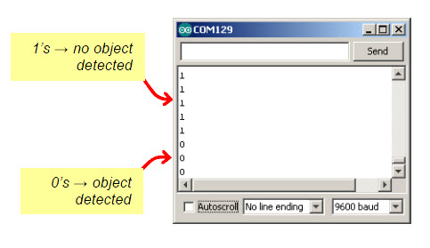
  • Leave the BOE Shield-Bot connected to its programming cable,  and open the Serial Monitor when the sketch is done uploading.
  • Place an object, such as your hand or a sheet of paper, about an inch (2 to 3 cm) from the left IR object detector.
  • Verify that the Serial Monitor displays a 0 when you place an object in front of the IR object detector, and a 1 when you remove the object.
  • If the Serial Monitor displays the expected values for object not detected (1) and object detected (0), move on to the Your Turn section. 
  • If the Serial Monitor displays the expected values, go ahead and test the right IR Object Detector (below).  If not, go to the Troubleshooting section for help.

Your Turn – Test the Right IR Object Detector

Modifying the sketch to test the right IR object detector is a matter of replacing irLeft with irRight, and passing the correct pin numbers to the irDetect parameters to test the other circuit. Here’s a checklist of the changes:

  • Save the sketch TestLeftIr as TestRightIr.
  • Change pinMode(10, INPUT);  pinMode(9, OUTPUT) to pinMode(3, INPUT);  pinMode(2, OUTPUT).
  • Change int irLeft = irDetect(9, 10, 38000) to int irRight = irDetect(2, 3, 38000).
  • Change Serial.println(irLeft) to Serial.println(irRight).
  • Repeat the testing steps in this activity for the BOE Shield-Bot’s right IR object detector.  
  • If necessary, trouble-shoot any circuit or code entry errors.

Printer-friendly version
Activity 1: Build and Test the Object Detectors
Prev
Activity 2: Field Testing
Next

DISCUSSION FORUMS | PARALLAX INC. STORE

About | Terms of Use | Feedback: learn@parallax.com | Copyright©Parallax Inc. 2024

© 2026 Parallax Learn • Built with GeneratePress