Install the Cables
Installing the 3-pin cables into the booms of your ELEV-8 v3 can be tricky. It requires you to partially disassemble your ELEV-8 v3 and to work slowly and carefully as you feed cables through the booms.
It is possible to simply run the cables along the outside of the booms and zip-tie them. If you choose to zip-tie the cables to the outside of your ELEV-8’s booms, simply connect them in the same manner as you did when you tested them in a prior step.
To install the cables inside of the booms:
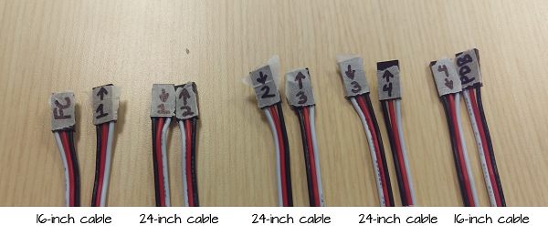
- Carefully lay out all 5 cables and label them as shown in the photograph below:
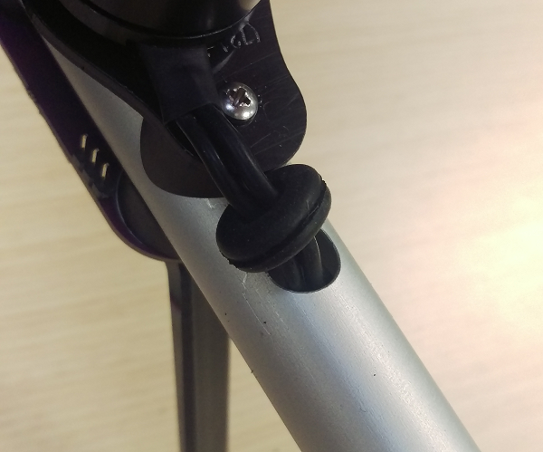
- Pull the grommet out of each boom and slide it towards the motor:
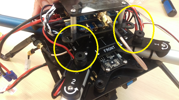
- Carefully pull the Flight Stack up and off of the four vibration dampers that attach it to the top chassis plate. Leave the vibration dampers in the top chassis plate as shown in the photograph below:
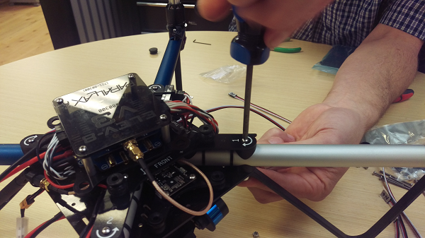
- Remove Boom #1 by removing the two screws that connect it to the chassis:
- Push the end of the first 16-inch 3-pin cable marked “FC” into the cable hole by the motor on Boom #1 through the boom until it comes out of the other end.
- Push the end of the first 24-inch 3-pin cable marked “2->” into the cable hole by the motor on Boom #1 through the boom until it comes out of the other end.
- Re-install Boom #1.
- Remove Boom #2 by removing the two screws that connect it to the chassis.
- Bend up the end of the cable 24-inch 3-pin cable marked “2->” as shown the photograph below:
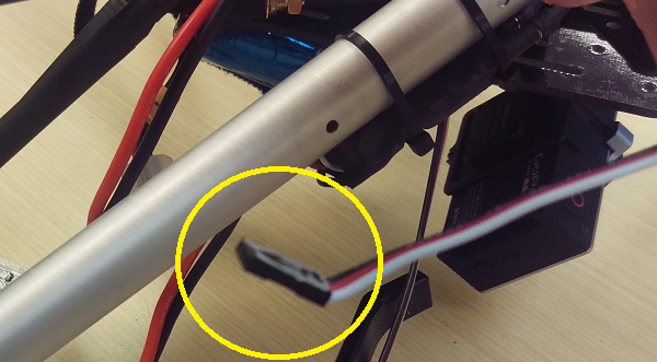
- Push that cable end into the chassis-side of Boom #2. Carefully watch into the hole where the motor wires enter to see when it reaches the motor end of the boom.
- Reach in and pull out the end of the cable; you may need to use a needle-nosed pliers for this.
- Push the end of the next 24-inch 3-pin cable marked “3->” into the cable hole by the motor on Boom #2 through the boom until it comes out of the other end.
- Re-install Boom #2.
- Remove Boom #3 by removing the two screws that connect it to the chassis.
- Bend up the end of the cable 24-inch 3-pin cable marked “3->”.
- Push that cable end into the chassis-side of Boom #3. Carefully watch into the hole where the motor wires enter to see when it reaches the motor end of the boom.
- Reach in and pull out the end of the cable; you may need to use a needle-nosed pliers for this.
- Push the end of the next 24-inch 3-pin cable marked “4->” into the cable hole by the motor on Boom #3 through the boom until it comes out of the other end.
- Re-install Boom #3.
- Remove Boom #4 by removing the two screws that connect it to the chassis.
- Bend up the end of the cable 24-inch 3-pin cable marked “4->”.
- Push that cable end into the chassis-side of Boom #4. Carefully watch into the hole where the motor wires enter to see when it reaches the motor end of the boom.
- Reach in and pull out the end of the cable; you may need to use a needle-nosed pliers for this.
- Push the end of the next 24-inch 3-pin cable marked “PDB” into the cable hole by the motor on Boom #4 through the boom until it comes out of the other end.
- Re-install Boom #4.
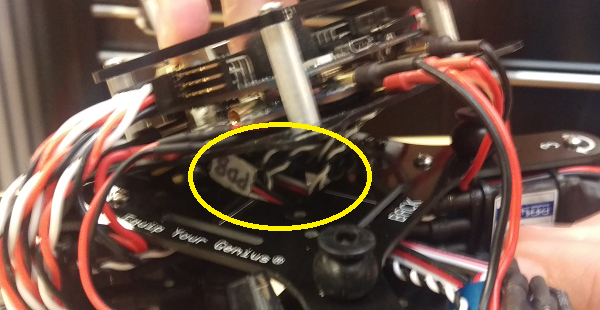
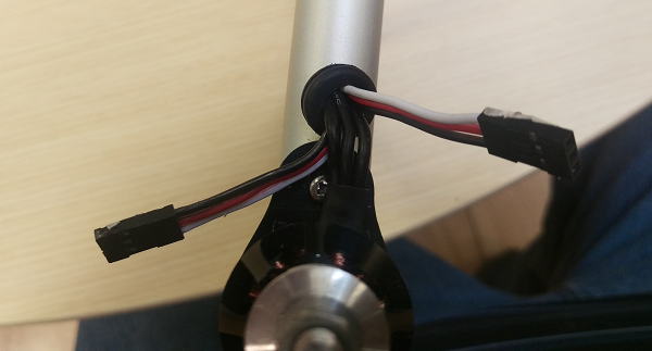
- Pull the end of the 3-pin cable marked “PDB” up through the center of the chassis as shown in the photograph below:
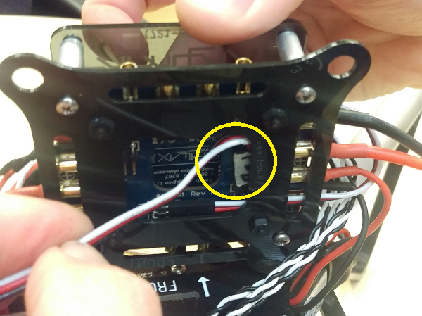
- Connect the cable to one of the 3-pin headers on the Power Distribution Board as shown as the photograph below:
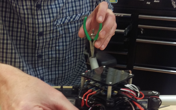
- Reinstall the Flight Stack back on the vibration dampers. Gentle use of needle-nose pliers can help with this, but be careful not to tear them.
- Pull the ends of the cables through the grommet on each boom:
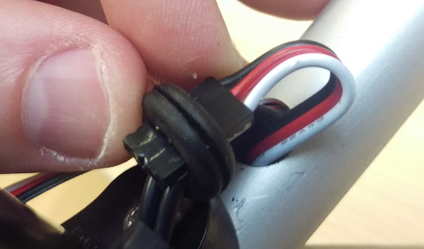
- Re-install the grommets.
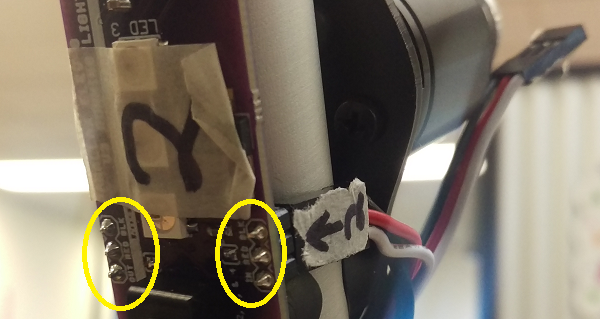
- Carefully connect the 3-pin cables to the Running Lights. Pay close attention to the labels on both the cables and the Running Light PCBs. Match the wire colors and direction to the labels:
- Once you have verified all of the connections and fully reassembled your ELEV-8 v3, remove the masking tape labels on the PCBs and cables.