Skip to content
Parallax Learn

Parallax Learn

  • Welcome
  • Tutorials
        • Tutorial Series head tag

          Tutorial Series
        • Tutorial Series

          The special, classroom-ready series pages are organized collections of tutorials for our most popular hardware and/or languages. The tutorials for each topic are conveniently accessible from a single page, shown in the order it is recommended that they be completed.
        • Robotics Series Head tag

          Robotics Series
        • Robotics Series

          • Artificial Intelligence
          • Cybersecurity: Radio Data tutorialCybersecurity
          • cyber:bot + Python
          • cyber:bot + MakeCode
          • Boe-Bot Tutorial SeriesBoe-Bot
          • Arduino Shield-Bot
          • ActivityBot with C TutorialsActivityBot + C
          • ActivityBot with BlocklyProp Tutorial SeriesActivityBot + BlocklyProp
          • Scribbler 3 Tutorial SeriesScribbler 3
        • Electronics & Programming Series Head tag

          Electronics & Programming Series
          • BS2 Board of Education Tutorial SeriesBS2 Board of Education
          • Propeller C-Language BasicsPropeller C Basics
          • FLiP Try-It Kit C Tutorial SeriesFLiP Try-It Kit + C
          • FLiP Try-It Kit BlocklyProp TutorialsFLiP Try-It Kit + BlocklyProp
          • Badge WX Tutorial SeriesBadge WX
          • Propeller BlocklyProp Basics and ProjectsPropeller BlocklyProp Basics
          • View All Tutorial Series »
        • Browse Tutorials
        • Browse Tutorials

          Individual tutorials sorted by robot or kit, and language.
        • By Robot or Kit
          • ActivityBot
          • SumoBot WX
          • Boe-Bot
          • Shield-Bot
          • cyber:bot
          • Badge WX
          • ELEV-8
          • ARLO
        • By Language
        • By Language

          • Propeller C
          • Arduino
          • BlocklyProp
          • PBASIC
          • Python
          • MakeCode
          • View All Tutorials »
  • Educators
  • Reference
  • Downloads
  • Home
  • All Courses
  • Sense Pushbutton Presses

Sense Pushbutton Presses

Build and Test a Pushbutton

As mentioned earlier, sometimes the two pushbuttons on the micro:bit just aren’t enough!  If this ever happens with your inventions and prototypes, it helps to be able to add more to a breadboard.  

In this activity, you will:

  • Build and test a pushbutton circuit.
  • Write scripts that monitor the pushbutton circuit through a micro:bit I/O pin.
  • Write scripts that perform different actions that depend on whether or not the pushbutton is pressed.

Parts

These are the parts you will add to the setup you started with in Setup from Previous Activities.

(1) Resistor – 220 Ω  (red-red-brown-gold)
(1) Resistor – 10 kΩ  (brown-black-orange-gold)
(1) Jumper wires – red
(1) Pushbutton – New part, see Pushbutton diagram

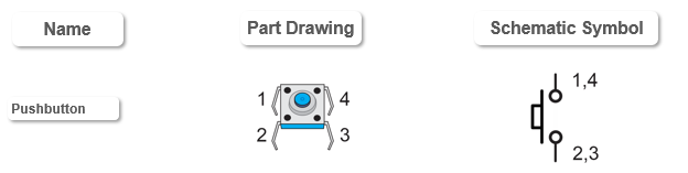
A part drawing with numbers by each pin is called a pin map.  Pin maps are normally published in part datasheets.  Engineers and technicians use schematics and pin maps when designing, troubleshooting, and maintaining circuits.  The schematic shows how the parts are interconnected, and the pin map shows how the pin numbers in the schematic relate to the physical part.  This pushbutton can be rotated 180°, and the pin map still applies.  That’s not common!  Most parts have a reference mark by pin 1 and cannot be rotated, for example the two black chips, an 8-pin op amp and a 3-pin transistor from your kit.
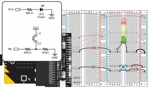
Circuit

  • Unplug the USB cable from your micro:bit.
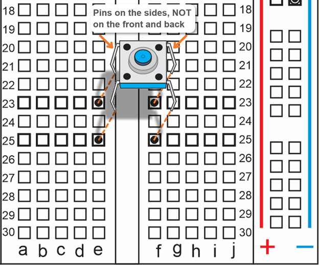
  • Orient the pushbutton so the legs are sticking out the sides of its body.
  • Double check: make sure the legs are coming out the sides, and not the front and back.
  • Set the pushbutton so that it’s legs are ready to sink into these right terminal strip sockets: pin 1 to (e, 23), pin 2 to (e, 25),  pin 3 to (f, 25), pin 4 (f, 23).
  • Press down firmly.  The legs should sink far enough into the sockets so that the pushbutton’s body rests on the breadboard.


  • Connected the pushbutton’s lower-left pin 2 to the micro:bit’s P6 pin with a 220 Ω resistor.
  • Connect the pushbutton’s lower-right pin 3 to the right bus strip’s blue (-) column with a 10 kΩ resistor (brown-black-orange-gold).
  • Connect the pushbutton’s upper-right pin 4 to the right bus strip’s red (+) column with a red jumper wire.
  • Reconnect the USB cable to your micro:bit module.


Printer-friendly version
Setup from Previous Tutorials
Prev
Script and Tests
Next

DISCUSSION FORUMS | PARALLAX INC. STORE

About | Terms of Use | Feedback: learn@parallax.com | Copyright©Parallax Inc. 2024

© 2025 Parallax Learn • Built with GeneratePress