Skip to content
Parallax Learn

Parallax Learn

  • Welcome
  • Tutorials
        • Tutorial Series head tag

          Tutorial Series
        • Tutorial Series

          The special, classroom-ready series pages are organized collections of tutorials for our most popular hardware and/or languages. The tutorials for each topic are conveniently accessible from a single page, shown in the order it is recommended that they be completed.
        • Robotics Series Head tag

          Robotics Series
        • Robotics Series

          • Artificial Intelligence
          • Cybersecurity: Radio Data tutorialCybersecurity
          • cyber:bot + Python
          • cyber:bot + MakeCode
          • Boe-Bot Tutorial SeriesBoe-Bot
          • Arduino Shield-Bot
          • ActivityBot with C TutorialsActivityBot + C
          • ActivityBot with BlocklyProp Tutorial SeriesActivityBot + BlocklyProp
          • Scribbler 3 Tutorial SeriesScribbler 3
        • Electronics & Programming Series Head tag

          Electronics & Programming Series
          • BS2 Board of Education Tutorial SeriesBS2 Board of Education
          • Propeller C-Language BasicsPropeller C Basics
          • FLiP Try-It Kit C Tutorial SeriesFLiP Try-It Kit + C
          • FLiP Try-It Kit BlocklyProp TutorialsFLiP Try-It Kit + BlocklyProp
          • Badge WX Tutorial SeriesBadge WX
          • Propeller BlocklyProp Basics and ProjectsPropeller BlocklyProp Basics
          • View All Tutorial Series »
        • Browse Tutorials
        • Browse Tutorials

          Individual tutorials sorted by robot or kit, and language.
        • By Robot or Kit
          • ActivityBot
          • SumoBot WX
          • Boe-Bot
          • Shield-Bot
          • cyber:bot
          • Badge WX
          • ELEV-8
          • ARLO
        • By Language
        • By Language

          • Propeller C
          • Arduino
          • BlocklyProp
          • PBASIC
          • Python
          • MakeCode
          • View All Tutorials »
  • Educators
  • Reference
  • Downloads
  • Home
  • All Courses
  • Sense Pushbutton Presses

Sense Pushbutton Presses

How it Works

How the Pushbutton Works

Looking inside the pushbutton, the legs that stick out of both sides of the pushbutton’s body are actually wires that pass all the way through.  One of the wires forms legs 1 and 4, and the other forms legs 2 and 3.  The button has a metal bar attached underneath and a springy material that keeps it floating above the two wires.  When you press the button, the metal bar comes to rest atop the two wires.  

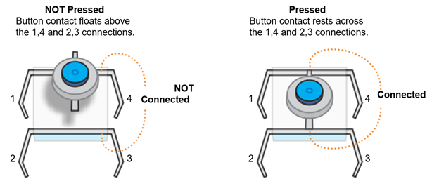
Since legs 1 and 4 are actually part of a single wire, they are always electrically connected, so a micro:bit continuity test will always display the checkmark.  The same applies to legs 2 and 3.  

When the button is not pressed, current cannot conduct between the 1,4 and 2,3 legs, so its connection is called open or an open circuit.  When the button is pressed, current can conduct between the 1,4 and 2,3 legs, and the connection is called closed.  Since this pushbutton is open when it is not pressed, it is called a normally open pushbutton.  Though your kit does not have them, normally closed pushbuttons also exist, where their connection is closed when it is not pressed, and open when it is pressed.

When the button is not pressed, legs 1 and 4 are insulated from 2 and 3.  So probing any of these pairs of pins will result in the micro:bit continuity tester’s LED display showing the not connected X: (4, 3), (4, 2), (1, 2), (1, 3).  When you press and hold the pushbutton, the micro:bit continuity tester displays the connected checkmark instead.

Try This

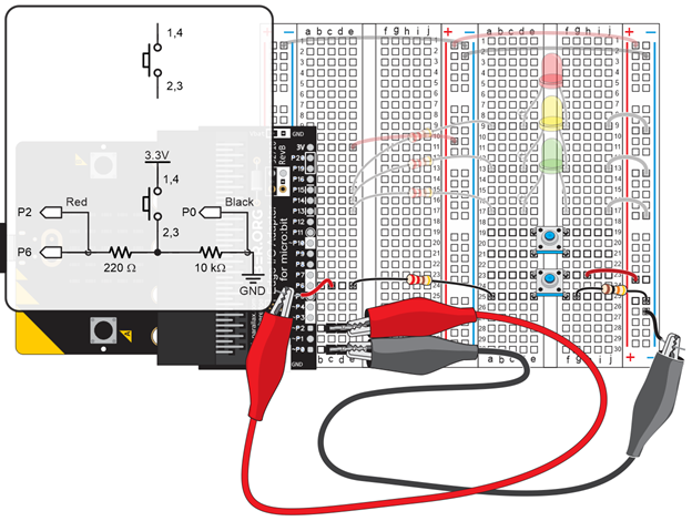
In addition to checking pushbutton functionality with continuity tests, sometimes the voltage it applies to the micro:bit needs to be checked.  In prototype tests and machine repairs, this is one of the first tests when pressing a button does not produce the desired result.

  • Right-click measure_volts_with_cyberscope and select Save link as… to download it.

measure_P6_volts_with_cyberscope.hex

  • Go to python.microbit.org/v/2.
  • Click Load/Save and then drag the file you just downloaded and drop it on the gray box in the Load section.  
  • Click the Flash button to load the script into the micro:bit.
  • Click Disconnect.

  • Go to cyberscope.parallax.com and click Connect.
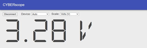
  • Press and hold the pushbutton for several seconds and verify that the voltage measurement is close to 3.3 V.

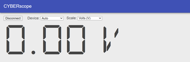
Release the pushbutton and verify that the measurement returns to a value close to 0 V.

  • In the CYBERscope, click Disconnect.


Printer-friendly version
Script and Tests
Prev
Active vs Resting States
Next

DISCUSSION FORUMS | PARALLAX INC. STORE

About | Terms of Use | Feedback: learn@parallax.com | Copyright©Parallax Inc. 2024

© 2025 Parallax Learn • Built with GeneratePress