2-Axis Joystick
2-Axis Joystick
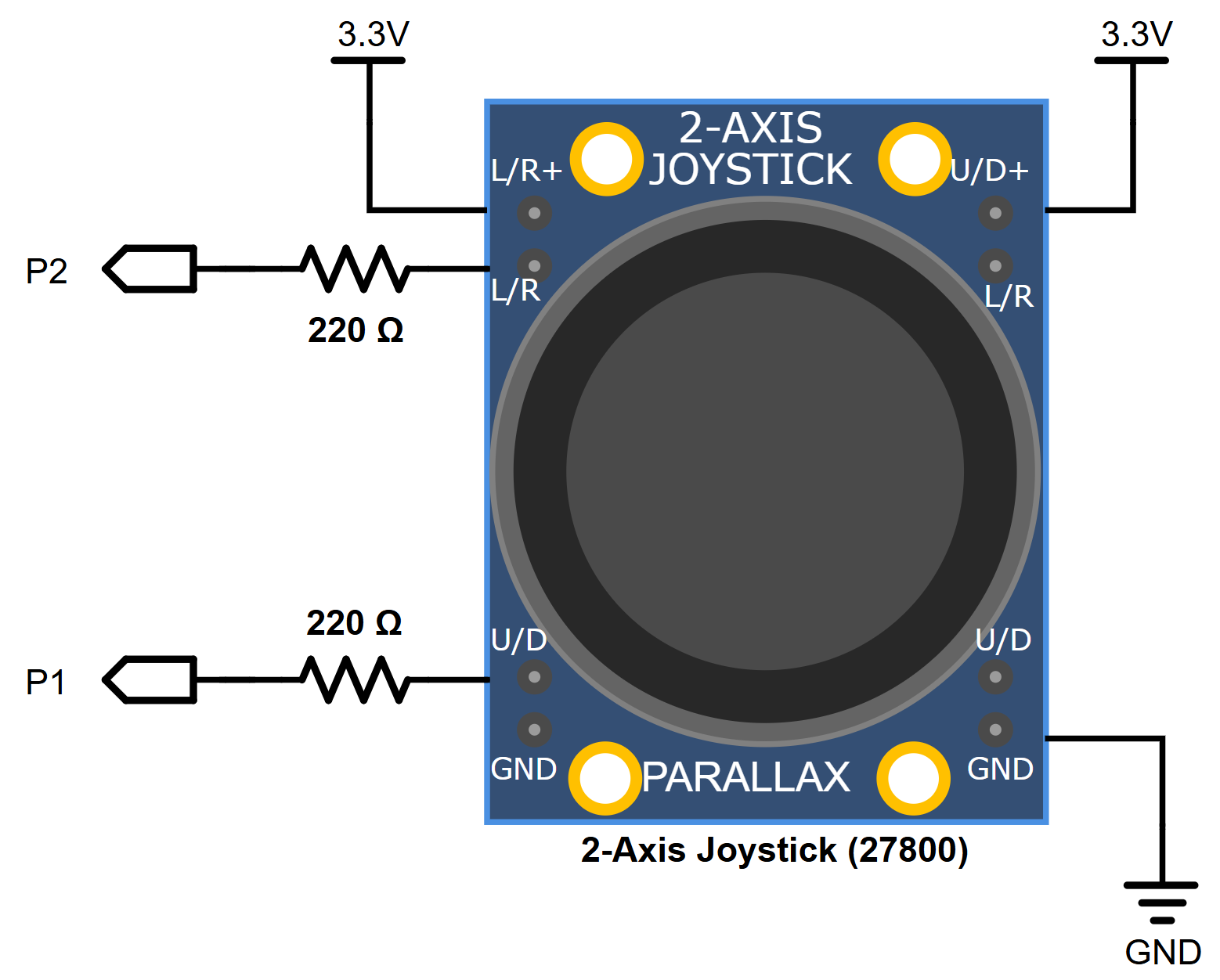
The 2-Axis Joystick’s position is measured by two potentiometers, one for the forward and backward motion and the other for left and right.
Parts
(1) 2-Axis Joystick 27800
(2) Resistor 220 Ω (red-red-brown-gold)
Jumper wires: (2) Red, (1) black
Schematic
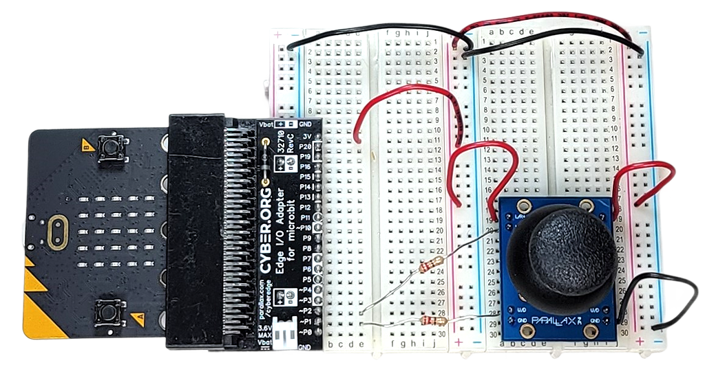
Wiring
Script
# joystick-measure-pot-volts-x2
from microbit import *

pin2.set_pull(pin2.NO_PULL)
pin1.set_pull(pin1.NO_PULL)

while True:
    adc_h = pin2.read_analog()
    v_h = adc_h * 3.3 / 1024
    adc_v = pin1.read_analog()
    v_v = adc_v * 3.3 / 1024

    s = "h:%.1f" % v_h + "V | " + "v:%.1f" % v_v +"V"
    print(s)
    display.scroll(s)
Tests
Use read_two_line_variable_voltage_sensor at the beginning of this section to measure the sensor’s voltage output.
After loading the script into the micro:bit, click Show serial in the micro:bit Python Editor. There, you will see the voltage measurements updated every second.
Script
# joystick-matrix-pixel-control

from microbit import *

def map(val, from_start, from_end, to_start, to_end):
    return (val-from_start)*(to_end-to_start)\
    /(from_end-from_start)+to_start

pin2.set_pull(pin2.NO_PULL)
pin1.set_pull(pin1.NO_PULL)

while True:
    adc_h = pin2.read_analog()
    h = int(map(adc_h, 0, 1024, 0, 5))
    adc_v = pin1.read_analog()
    v = int(map(adc_v, 0, 1024, 0, 5))
    display.clear()
    display.set_pixel(v, h, 9)
    sleep(20)
Tests
Verify that the “pixel” on the micro:bit module’s 5×5 LED matrix display lights up and indicates the position of the joystick.