Extra Parts for FLiP Kit
If you are using the Propeller FLiP Try-it Kit, you can add additional parts to this project, using the extra breadboard space and free Propeller I/O pins.
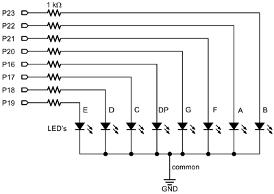
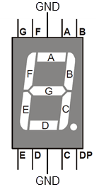
A 7-segment LED display (left) visually indicates the direction of tilt by lighting up the segments that correspond to the lowest edge of the breadboard. See the Seven-Segment Display tutorial to learn more about how this device works.
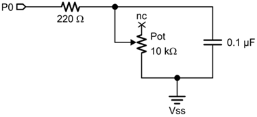
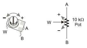
A potentiometer (right) will let you adjust the tempo all you want during run-time just by twisting the potentiometer’s knob. You will not need to modify the set variable beat block and reprogram your FLiP module just to change the tempo. You can learn more about the potentiometer and this circuit from the Potentiometer Position page in the Circuit Practice with BlocklyProp tutorial.
Additional parts needed
- (1) 7-segment LED (# 350-00027)
- (8) 1 k-ohm resistors, brown-black-red
- (1) 10 k-ohm potentiometer (# 152-01031)
- (1) 0.1 µF capacitor, marked 104
- (1) 220-ohm resistor, red-red-brown
- (misc) jumper wires
I/O Pin Assignments
- P0 — potentiometer
- P16-P23 — 7-segment LED
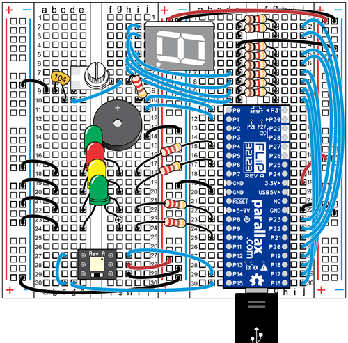
Build the New Circuits
- Disconnect power from your Propeller FLiP module.
- Build the potentiometer circuit in the position shown in the wiring diagram below.
- Optionally build the 7-segment LED circuit. Note that the I/O pin numbers are not sequential.