RC-time and Voltage Decay
The charge transfer measurement is done with these two lines of code:
    bot(8).write_digital(1)
    qt_left = bot(8).rc_time(1)
The first line, bot(8).write_digital(1), does two things. First, it charges the capacitor by setting Propeller I/O pin P8 to output high (3.3 volts). Then, it waits one millisecond for the capacitor to fully charge – more than enough time for this tiny one.
The next line, qt_left = bot(8).rc_time(1), is doing a lot more. The rc_time function:
- Marks the time on the Propeller system clock.
- Sets P8 to an input, which allows the charge in the capacitor to start draining.
- Watches the voltage sensed at P8 Remember, P8 is a digital I/O pin; instead of sensing a range of analog values, it reports either a high (1) or a low (0) signal with 1.6 volts being the threshold in between.
- Marks the time again when the signal at P8 changes from 1 to 0.
- Subtracts the first time marked from the second time marked. The result is how long it took capacitor to discharge from 3.3 V to the 1.6 V voltage threshold.
- Stores the discharge time in the variable qt_left.
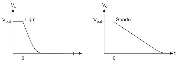
Look Deeper: Voltage Decay Graphs
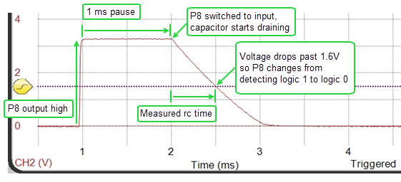
Here is an example of a charge transfer measured with an oscilloscope, a device that displays voltage as it changes over time. The vertical axis on the left is volts, and time increases by milliseconds along the bottom.
The red line that’s graphing voltage is called a trace. The trace plots the capacitor’s voltage in the P8 QT circuit; that’s the left light sensor. In response to bot(8).write_digital(1), the voltage quickly rises from 0 V to almost 3.3 V at about the 1 ms mark, and stays there for 1 millisecond. Then, at the 2 ms mark, the rc_time call allows the voltage in the capacitor to start draining, or “decay.” The rc_time function measures the time it takes the voltage to decay to the Propeller I/O pin’s logic threshold of about 1.6 V. This measured rc decay time gets stored in the qt_left variable. In the plot, it looks like that decay took about 1 ms, so the qt_left variable would store a value close to 1000.
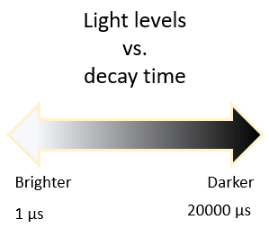
Keep in mind that these are not the voltage measurements from Activity 1, they are time measurements. When the voltage decay takes a short time the number will be small, and that means bright light. When the voltage decay takes a long time, the number will be larger, and that means dimmer light, shade, or for really large numbers, darkness.
Keep in mind that these are not the voltage measurements from Activity 1, they are time measurements. When the voltage decay takes a short time the number will be small, and that means bright light. When the voltage decay takes a long time, the number will be larger, and that means dimmer light, shade, or for really large numbers, darkness.