Test the Light Sensor Eyes
Example project: left_light_sensor
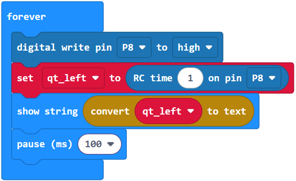
The project left_light_sensor charges the capacitor in the P8 circuit, measures the time it takes for the capacitor to discharge, and displays that value on the micro:bit module’s LED matrix. Remember, with this circuit and project, lower numbers mean brighter light now!
- Put the cyber:bot board’s power switch in position 1.
- Enter and flash the project left_light_sensor.
- Point your cyber:bot towards the room’s light source, then shade the left phototransistor with your hand.
- Watch the micro:bit module’s display. It should be showing numbers between 0 and about 200, with brighter light making for smaller numbers. If not, check wiring and rerun the program.
Your Turn
The other phototransistor circuit on the right side of the robot also needs testing!
- Duplicate the project left_light_sensor as right_light_sensor.
- Change both of the Pin8 commands to Pin6.
- Change the variable qt_left to qt_right in both places.
- Flash the project to your micro:bit module.
- Make sure the micro:bit module’s display is changing its numbers as you point the right phototransistor towards the light source and then shade it with your hand.
These steps are important!
Your circuits and code must pass these tests before continuing. The rest of the examples in this chapter rely on both light sensors working correctly.