Here on the southern Oregon coast, cranberry growing is a significant part of the local economy. Commercially grown cranberries are, however, subject to the vagaries of our somewhat unpredictable coastal weather. Frost in particular can devastate a crop if protective measures are not taken. One of the most common frost protection measures is to run the irrigation sprinklers during times of frost. The relatively warmer water helps to keep the berries from freezing.
My cranberry-growing friend had a problem. Although his irrigation pump was a 20 horsepower submersible, it did not have the capacity to irrigate all five of his bogs simultaneously. This was not a problem during normal temperatures. The five bogs could be irrigated one at a time over a one hour cycle, and the pump was quite adequate for this mode of watering. But when frost conditions arrived, his crop was in trouble. The solution was to initiate a five minute on, ten minute off rapid cycle of watering. Since the first bog was twice the size of the remaining four, it was watered first and then the remaining four were watered in sets of two for the remainder of the cycle. Producing this new cycle required the ability for the irrigation control system to monitor and respond to four sets of possible conditions presented by two voltage sources. Accomplishing this task reliably was proving difficult using analog circuits. But this is just the sort of task for which the BASIC Stamp was born!
We had the Stamp look at two inputs, either of which could be at a logic high (5 volts) or a logic low (0 volts). The sprinkler had to turn on only when both inputs were high, and to remain on until both inputs went low. If in the off condition, the pump was not to start if only one of the inputs went high, and if running, it was not to turn off if only one of the inputs went low. Writing the code to respond to these conditions required a surprisingly small amount of code:
' {$STAMP BS2}
' {$PBASIC 2.5}

' Program to control Don's cranberry bog pump
' Program watches two 24 volt inputs (reduced to 5 volts by the time it reaches the stamp)
' When both 24 volt inputs are on then the solid state relay will go on
' The solid state relay will stay on until both 24 volt inputs go off.
' Bog Pump 1.bs2
‘ Uncomment DEBUG statements to turn on debugging

check VAR Byte                           ’ variable for debug output

DO                                       ’ Loop to watch the two 24 volt inputs

  IF( IN3 = 1 AND IN1 = 1) THEN          ’ If both 24 volt inputs are on
     HIGH 12                             ’ Turn solid state relay on
     check = 1
     ’DEBUG  DEC check                   ’ Send condition state to terminal for debugging information
  ELSEIF( IN3 = 0 AND IN1 = 0) THEN      ’ Only turn solid state relay off if both 24 volt inputs are off
      check = 0
      ’DEBUG DEC check                   ’ Send condition state to terminal for debugging information
      LOW 12                             ’ Turn solid state relay off

      ’....................Debugging Code..............................
’ This is useful if you have bad connections
  ELSEIF( IN3 = 0 AND IN1 = 1) THEN     ’ These are just debugging lines to show
      check = 2                         ’ what is happening on other 2 possible combinations of input
                                        ’   ’ line voltages
      ’DEBUG DEC check                  ‘ Send condition state to terminal for debugging information
  ELSEIF( IN3 = 1 AND IN1 = 0) THEN
      check = 3                         ...
      ’DEBUG DEC check                   ’ Send condition state to terminal for debugging information
                                        ...
  ENDIF                                  ’ End the if then section
       ’..................End of Debugging Code.........................

LOOP                                     ’ Go back and look at the 24 volt inputs again
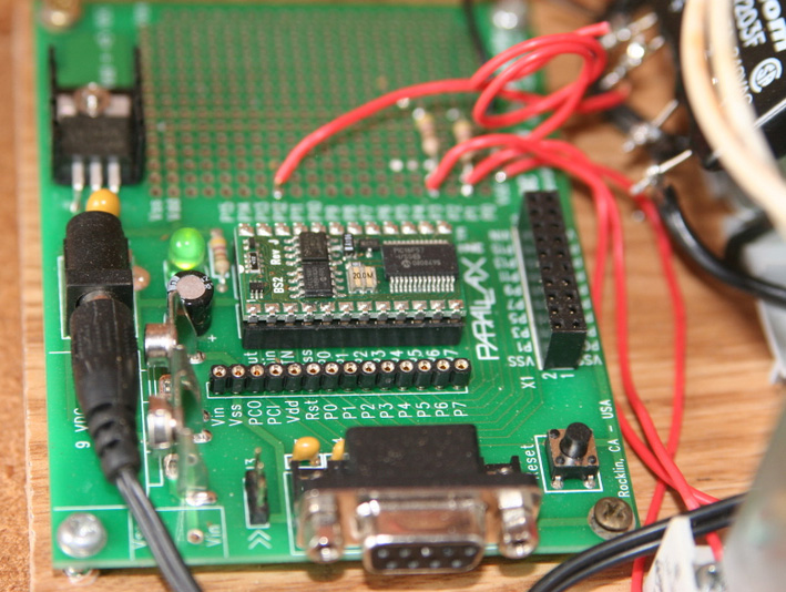
Electrically interfacing the Stamp to the rest of the system proved to be relatively simple as well. The inputs from the rest of the system were in the form of 24 volt alternating current signals. We opted for the simple, if not particularly elegant, solution of installing a pair of small 24 volt coil relays on the inputs and using them to switch a 5 volt direct current source to provide inputs in a form compatible with the Stamp’s TTL requirements. On the output side, we used a Crydom 2DW solid state relay. This relay uses the 5 volt output of the BASIC Stamp to switch a 300 watt 120 volt AC current. The output of this solid state relay is more than sufficient to activate the large power relay which controls the 20 horsepower submersible irrigation pump. In the photos, the cover of the Stamp control unit is removed for clarity.
The only troubleshooting situation that we encountered was due to the fact that initially we did not configure our Stamp inputs in a pull-down, active high configuration. The Stamp proved to have a high enough input impedance that we could activate the system by merely waving a hand over the electrically floating input wires. Once we went to the pull-down, active high configuration, with a high value resistor pulling the inactivated input down to ground, the problem was solved. The system has been installed for several months now and has worked flawlessly. Thanks to Parallax for a great product!