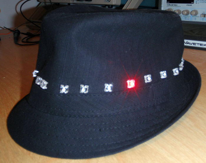
A jaunty fedora ringed with high output LEDs that blink red in alternating patterns using an Arduino hidden within the hat. Designed to celebrate any holiday or party. I have worn it to a few and it is definitely an eye-grabber.
The “brains” of the hat is the Arduino microcontroller. For me the Arduino was great because it had a lot of documentation and I had worked with it before. It also required very few external components to get working so it was easy to fit inside of the hat.
My main reason for building this hat was to experiment with a multiplexing scheme that I had been reading about, charlieplexing. I had done traditional multiplexing before but charlieplexing had this appeal to me because it required so few pins. I wanted to see how well this scheme worked and especially experiment with using it to display different patterns because of the low duty cycles it had to use because it turned each LED on one by one.
Charlieplexing makes use of three state logic and the fact that there is a voltage drop across LEDs. It requires that you turn some pin high and another low and the rest go into a high impedance state to appear unconnected to the circuit. If the LEDs are arranged in the correct configuration, it allows you to individually address any LED. This allows you to use a minimum amount of pins. For traditional multiplexing schemes, you must use “2n” pins to drive “n2” LEDs. This is good for most applications and sure beats wiring each LED individually, but, if you want to drive the most LEDs with the fewest amount of pins charlieplexing is the better choice. In a charlieplexed display you can drive “n(n-1)” LEDs with “n” pins. Because of this, charlieplexing is much more efficient the more LEDs you use. However, it does have its limitations. Because it only turns on one LED at a time, it has a very low duty cycle making driving many LEDs impractical if you are trying to make a design that relies on persistence of vision.
In this hat there are 22 LEDs around it. This meant that I had to use at least 6 pins. This also means that I could have driven up to 30 LEDs without much difficulty but it looked too crowded on the hat. Each LED is a high output 4 pinned red LED and is wire wrapped into place. I chose to wire wrap the LEDs in instead of soldering because I was afraid of burning the hat. To hold the Arduino, I made a printed circuit board that I designed and milled it at my school. I then soldered on the Arduino and the necessary components and attached the appropriate pins to the LEDs.
To power the hat I initially used 9V batteries, but, after I ran through a few I decided to go to the cheaper AA batteries which also have the added benefit of lasting longer. The batteries go into a voltage regulator which drops the voltage to 5V for the Arduino.
To program the Arduino I use another actual Duemilanove board which has the FTDI chip that allows communication from a USB port and program the hat Arduino by hooking the correct pins together and then uploading the sketch.
As of now the hat runs through a list of different patterns and just repeats. These patterns are: (1) a lone LED circling the hat, (2) then it speeds up, (3) all the LEDs appear to turn on and flash, (4) a snake circles the hat, (5) a download progress bar, and (6) every other LED turns on and then it appears to spin. My next step for this project is to add sensors to dictate when to switch designs.