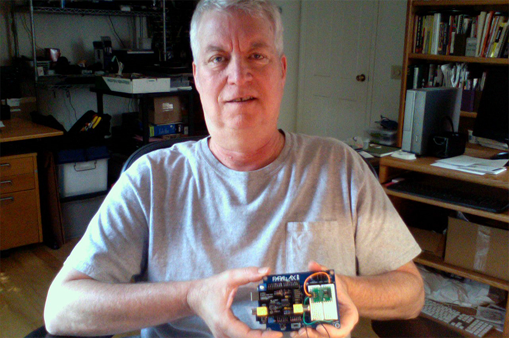
The genus of my microMedic entry was a request from a research partner to overlay vital-sign readings (oxygen saturation and heart rate) on an existing video image of a patient being viewed in real-time over an internet video connection using our dedicated video endpoint that we call the DocBox. These units have been used for tele-exercise programs for participants who are managing chronic conditions such as chronic obstructive pulmonary disease (COPD), and diabetes, or those who have a fallen or have a fear of falling. We would like to see each participant’s heart rate and blood-oxygen saturation appear in a corner of their screen image.
Having had some prior exposure to the Arduino, I applied for an Arduino Board of Education (BOE) kit. Given the relatively short time frame, (I started work on the contest in mid-June), it seemed prudent to limit the objectives of the contest entry to what was probably the easiest sensor (the heart rate monitor), and to investigate ways of overlaying the received heart rate data on to a video image.
Materials
I chose four components from the microMedic Arduino BOE kit:
- Arduino BOE
- Polar WearLink Heart Rate Transmitter
- Heart Rate Receiver
- 4-Digit 7-segment LED display
During the evolution of the project, the components were augmented with the Nootropic Video Experimenter board which ultimately provided the data overlay on the TV.
The project uses the Arduino Uno. As mentioned in the discussion section, it is an open question whether another platform may be more suitable. The Arduino Mega has a higher processing speed, the Rasberry Pi includes HDMI already configured on its PCB, and the Propeller has the ability to run independent processes that would allow separation of the sensor monitoring code and the television display code. (The latter will become more critical as additional sensors are added).

