The user’s control interface consists of a development board with one joystick and six buttons to control the remote system. The joystick allows the camcorder system to be controlled with 2 axes: pan (Left/Right) and tilt (Up/Down). The six buttons consist of four buttons to control the camcorder (Record, Display on/off, Zoom In, and Zoom Out) and two buttons for speed settings (Increase Speed and Decrease Speed). The control interface also includes two displays, the Tilt Position Indicator and the Speed Indicator. The Tilt Position Indicator simply consists of 8 in-line LEDs which light up in sequence to specify how far up or down the camcorder is tilted (the more LEDs lit, the farther up the camcorder is tilted). The Speed Indicator involves the 7-segment LED display to reveal the current motor speed for the remote system; “1” indicates the slowest speed setting while “4” is the fastest. I realized when heavily zoomed with the camcorder, a standardized, set speed setting would make the camcorder appear to be panning and tilting faster than it truly were. Therefore by implementing four different speed settings, the user can better control and choose how fast the camcorder will move by making the joystick appear to have several sensitivity settings.
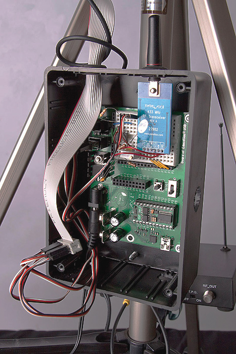
The remote system consists of a tripod equipped with the motorized camcorder mounting bracket, camcorder, system electronics enclosed in a project box, and video sender. After receiving the control signals from the “master” system, the “slave” system does a minimal amount of processing to interpret how to control the various camcorder components. The system decodes any camcorder control for the Infrared (IR) LED, sends the appropriate Panning signals to the motor, sends the appropriate Tilting signals to the motors, then sends appropriate control signals to the IR LED to control the camcorder. The camcorder uses a composite video output port to send the video signal to the video sender, which then sends the signal over the air to be received by the user’s TV tuner/video display. With this implementation, the user can see exactly what the camcorder is doing and recording. Without these components, this system would be as good as a person driving a vehicle with an opaque windshield; the user needs to have feedback from the remote system to determine how to properly control the system.