")
Item code: 27911
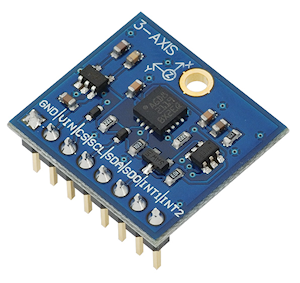
What It Can Do
- Modular angular rate sensor tracks motion in three axes
- Three selectable measurement scales, with rates up to 2000° per second
- Built-in temperature sensor; can be used separately, or for temperature drift compensation
The 3-Axis Gyroscope module provides separate data values for yaw, pitch, and roll. Motion is indicated as a positive or negative value, depending on the direction of rotation. The sensor is useful in 3D simulation, virtual gaming input devices, robotics, and for remotely controlled or unpiloted aircraft and submersibles.

Gyroscopes are commonly used with multi-axis accelerometers, where the data from both sensors can provide useful information detailing speed and direction of travel. The Memsic 2125 Dual-axis Accelerometer and MMA7455 3-Axis Accelerometer Module are good companion accelerometers for the 3-Axis Gyroscope module
It may also be used with an accelerometer and 3-axis compass to construct a 9-axis IMU (intertial measurement unit), common in unmanned aerial vehicles, such as drones and quadcopters.
Parts List
- 3-Axis Gyroscope module
- BASIC Stamp HomeWork Board, Propeller BOE, Propeller QuickStart, or Arduino Uno microcontroller (with breadboard, as needed)
- 22 gauge solid conductor hookup wire
Basic Wiring

- Power Requirements: 2.7 to 6.5 VDC
- Communication Interface: I2C (up to 400 kHz) or SPI (10 MHz; 4 & 3 wire)
- Dimensions: 0.85 X 0.80 in (2.16 X 2.03 cm)
Program KickStarts
The KickStart examples display raw data output for each of the three axes. Values are retrieved from the module using the I2C interface.
BASIC Stamp HomeWork Board

Download BASIC Stamp 2 code for the 3-Axis Gyroscope Module
' {$STAMP BS2}
' {$PBASIC 2.5}
SDA PIN 0 ' SDA of gyro connected to P0
SCL PIN 1 ' SCL of gyro connected to P1
WRITE_Data CON $D2 ' Request Write operation
READ_Data CON $D3 ' Request Read operation
' Control registers
CTRL_REG1 CON $20
CTRL_REG2 CON $21
CTRL_REG3 CON $22
CTRL_REG4 CON $23
STATUS_REG CON $27
OUT_X_INC CON $A8
X VAR Word
Y VAR Word
Z VAR Word
rawl VAR Word
rawh VAR Word
' Variables for I2C communications
I2C_DATA VAR Byte
I2C_LSB VAR Bit
I2C_REG VAR Byte
I2C_VAL VAR Byte
PAUSE 100 ' Power up delay
' Set up data ready signal
I2C_REG = CTRL_REG3
I2C_VAL = $08
GOSUB I2C_Write_Reg
' Set up "block data update" mode
I2C_REG = CTRL_REG4
I2C_VAL = $80
GOSUB I2C_Write_Reg
' Send the get continuous output command
I2C_REG = CTRL_REG1
I2C_VAL = $1F
GOSUB I2C_Write_Reg
DO
GOSUB Gyro_Get_Raw ' Get XYZ data
' Divide X Y Z, by 114 to reduce noise
IF (X.BIT15) THEN
X = (ABS X) / 114
X = -X
ELSE
X = X / 114
ENDIF
IF (Y.BIT15) THEN
Y = (ABS Y) / 114
Y = -Y
ELSE
Y = Y / 114
ENDIF
IF (Z.BIT15) THEN
Z = (ABS Z) / 114
Z = -Z
ELSE
Z = Z / 114
ENDIF
DEBUG HOME, "RAW X = ",11, SDEC X, CR ' Display data
DEBUG "RAW Y = ",11, SDEC Y, CR
DEBUG "RAW Z = ",11, SDEC Z, CR
PAUSE 250
LOOP
Gyro_Get_Raw:
GOSUB Wait_For_Data_Ready
GOSUB I2C_Start
I2C_DATA = WRITE_DATA
GOSUB I2C_Write ' Read the data starting
I2C_DATA = OUT_X_INC ' at pointer register
GOSUB I2C_Write
GOSUB I2C_Stop
GOSUB I2C_Start
I2C_DATA = READ_DATA
GOSUB I2C_Write
GOSUB I2C_Read
rawL = I2C_DATA ' Read high byte
GOSUB I2C_ACK
GOSUB I2C_Read
rawH = I2C_DATA ' Read low byte
GOSUB I2C_ACK
X = (rawH << 8) | rawL ' OR high and low into X
' Do the same for Y and Z:
GOSUB I2C_Read
rawL = I2C_DATA
GOSUB I2C_ACK
GOSUB I2C_Read
rawH = I2C_DATA
GOSUB I2C_ACK
Y = (rawH << 8) | rawL
GOSUB I2C_Read
rawL = I2C_DATA
GOSUB I2C_ACK
GOSUB I2C_Read
rawH = I2C_DATA
GOSUB I2C_NACK
Z = (rawH << 8) | rawL
GOSUB I2C_Stop
RETURN
'---------I2C functions------------
' Read the status register until the ZYXDA bit is high
Wait_For_Data_Ready:
DO
I2C_REG = STATUS_REG
GOSUB I2C_Read_Reg
LOOP UNTIL ((I2C_DATA & $08) <> 0)
RETURN
' Set I2C_REG & I2C_VAL before calling this
I2C_Write_Reg:
GOSUB I2C_Start
I2C_DATA = WRITE_DATA
GOSUB I2C_Write
I2C_DATA = I2C_REG
GOSUB I2C_Write
I2C_DATA = I2C_VAL
GOSUB I2C_Write
GOSUB I2C_Stop
RETURN
' Set I2C_REG before calling this, I2C_DATA will have result
I2C_Read_Reg:
GOSUB I2C_Start
I2C_DATA = WRITE_DATA
GOSUB I2C_Write
I2C_DATA = I2C_REG
GOSUB I2C_Write
GOSUB I2C_Stop
GOSUB I2C_Start
I2C_DATA = READ_DATA
GOSUB I2C_Write
GOSUB I2C_Read
GOSUB I2C_NACK
GOSUB I2C_Stop
RETURN
I2C_Start:
LOW SDA
LOW SCL
RETURN
I2C_Stop:
LOW SDA
INPUT SCL
INPUT SDA
RETURN
I2C_ACK:
LOW SDA
INPUT SCL
LOW SCL
INPUT SDA
RETURN
I2C_NACK:
INPUT SDA
INPUT SCL
LOW SCL
RETURN
I2C_Read:
SHIFTIN SDA, SCL, MSBPRE, [I2C_DATA]
RETURN
I2C_Write:
I2C_LSB = I2C_DATA.BIT0
I2C_DATA = I2C_DATA / 2
SHIFTOUT SDA, SCL, MSBFIRST, [I2C_DATA7]
IF I2C_LSB THEN INPUT SDA ELSE LOW SDA
INPUT SCL
LOW SCL
INPUT SDA
INPUT SCL
LOW SCL
RETURN
When this program is run the BASIC Stamp Debug Terminal will automatically open.
Propeller BOE and Propeller QuickStart

Propeller BOE Wiring Diagram

Propeller QuickStart Wiring Diagram
Download Propeller Spin code for the 3-Axis Gyroscope Module
OBJ

  pst          : "FullDuplexSerial"

CON

  _clkmode      = xtal1 + pll16x
  _clkfreq      = 80_000_000

  SDApin         = 0            ' SDA of gyro connected to P0
  SCLpin         = 1            ' SCL of gyro connected to P1

  WRITE         = $D2           ' Request Write operation
  READ          = $D3           ' Request Read operation

  ' Control registers
  CTRL_REG1     = $20
  CTRL_REG2     = $21
  CTRL_REG3     = $22
  CTRL_REG4     = $23
  STATUS_REG    = $27
  OUT_X_INC     = $A8

  x_idx = 0
  y_idx = 1
  z_idx = 2

VAR

  long x
  long y
  long z

  long cx
  long cy
  long cz

  long ff_x
  long ff_y
  long ff_z

  long multiBYTE[3]

PUB Go | last_ticks

  pst.start(31, 30, 0, 115200)

  ' Set modes
  Wrt_1B(CTRL_REG3, $08)                    ' Data ready signal
  Wrt_1B(CTRL_REG4, $80)                    ' Block data update
  Wrt_1B(CTRL_REG1, $1F)                    ' Enable all axes

  last_ticks := cnt

  repeat
    pst.tx(1)                               ' Set Terminal data
    WaitForDataReady 			        '  at top of screen
    Read_MultiB(OUT_X_INC)                  ' Read XYZ bytes

    ' Divide by 114 to reduce noise
    x := (x - cx) / 114
    y := (y - cy) / 114
    z := (z - cz) / 114

    RawXYZ
    WaitCnt(ClkFreq / 4  + Cnt)             ' Delay before next loop

PUB RawXYZ
  'Display Raw X,Y,Z data

  pst.str(string("RAW X ",11))
  pst.dec(x)

  pst.str(string(13, "RAW Y ",11))
  pst.dec(y)

  pst.str(string(13, "RAW Z ",11))
  pst.dec(z)


'' Below here routines to support I2C interfacing

PUB WaitForDataReady | status
    repeat
      status := Read_1B(STATUS_REG)
      if (status & $08) == $08
        quit

PUB Wrt_1B(SUB1, data)
  ''Write single byte to Gyroscope.

      start
      send(WRITE)
      send(SUB1)
      send(data)
      stop

PUB Read_1B(SUB3) | rxd
 ''Read single byte from Gyroscope

      start
      send(WRITE)
      send(SUB3)
      stop

      start
      send(READ)
      rxd := receive(false)
      stop

     result := rxd

PUB Read_MultiB(SUB3)
 ''Read multiple bytes from Gyroscope

     start
      send(WRITE)
      send(SUB3)
      stop

      start
      send(READ)
      multiBYTE[x_idx] := (receive(true)) |  (receive(true)) << 8
      multiBYTE[y_idx] := (receive(true)) |  (receive(true)) << 8
      multiBYTE[z_idx] := (receive(true)) |  (receive(false)) << 8
      stop

      x := ~~multiBYTE[x_idx]
      y := ~~multiBYTE[y_idx]
      z := ~~multiBYTE[z_idx]

PRI send(value)

  value := ((!value) >< 8)

  repeat 8
    dira[SDApin]       := value
    dira[SCLpin]       := false
    dira[SCLpin]       := true
    value >>= 1

  dira[SDApin]         := false
  dira[SCLpin]         := false
  result               := not(ina[SDApin])
  dira[SCLpin]         := true
  dira[SDApin]         := true

PRI receive(aknowledge)

  dira[SDApin]         := false

  repeat 8
    result <<= 1
    dira[SCLpin]       := false
    result             |= ina[SDApin]
    dira[SCLpin]       := true

  dira[SDApin]         := (aknowledge)
  dira[SCLpin]         := false
  dira[SCLpin]         := true
  dira[SDApin]         := true

PRI start

  outa[SDApin]         := false
  outa[SCLpin]         := false
  dira[SDApin]         := true
  dira[SCLpin]         := true

PRI stop

  dira[SCLpin]         := false
  dira[SDApin]         := false
To view the results of the demonstration, after uploading is complete run the Parallax Serial Terminal from the Run menu, or press F12. Click the Enable button in the Terminal window, then momentarily depress the Reset button on the Propeller QuickStart board to restart the program.
Arduino Uno

Download Arduino Code for the 3-Axis Gyroscope Module
#include <Wire.h>

#define CTRL_REG1 0x20
#define CTRL_REG2 0x21
#define CTRL_REG3 0x22
#define CTRL_REG4 0x23

int Addr = 105;                 // I2C address of gyro
int x, y, z;

void setup(){
  Wire.begin();
  Serial.begin(9600);
  writeI2C(CTRL_REG1, 0x1F);    // Turn on all axes, disable power down
  writeI2C(CTRL_REG3, 0x08);    // Enable control ready signal
  writeI2C(CTRL_REG4, 0x80);    // Set scale (500 deg/sec)
  delay(100);                   // Wait to synchronize
}

void loop(){
  getGyroValues();              // Get new values
  // In following Dividing by 114 reduces noise
  Serial.print("Raw X:");  Serial.print(x / 114);
  Serial.print(" Raw Y:"); Serial.print(y / 114);
  Serial.print(" Raw Z:"); Serial.println(z / 114);
  delay(500);                   // Short delay between reads
}

void getGyroValues () {
  byte MSB, LSB;

  MSB = readI2C(0x29);
  LSB = readI2C(0x28);
  x = ((MSB << 8) | LSB);

  MSB = readI2C(0x2B);
  LSB = readI2C(0x2A);
  y = ((MSB << 8) | LSB);

  MSB = readI2C(0x2D);
  LSB = readI2C(0x2C);
  z = ((MSB << 8) | LSB);
}

int readI2C (byte regAddr) {
    Wire.beginTransmission(Addr);
    Wire.write(regAddr);                // Register address to read
    Wire.endTransmission();             // Terminate request
    Wire.requestFrom(Addr, 1);          // Read a byte
    while(!Wire.available()) { };       // Wait for receipt
    return(Wire.read());                // Get result
}

void writeI2C (byte regAddr, byte val) {
    Wire.beginTransmission(Addr);
    Wire.write(regAddr);
    Wire.write(val);
    Wire.endTransmission();
}
To view the results of the demonstration, after uploading is complete click the Serial Monitor icon in the Arduino IDE. This displays the Serial Monitor window. Momentarily depress the Reset button on the Arduino board to restart the sketch.
For More Information
- See the 3-Axis Gyroscope (#27911) data sheet.
- More information on gyroscopes and inertial navigation may be found on Wikipedia: Gyroscope
- Combine the 3-axis gyroscope with the Parallax MMA7455 3-Axis Accelerometer Module and Compass Module 3-Axis HMC5883L to create a 9-axis inertial momentum unit (IMU)