")
This item is included in the 2013 National microMedic Contest Kit
What It Can Do
- Receives heart beat signals from a compatible sensor transmitter
- Indicates a received heartbeat signal using a LOW/HIGH output signal
- Wirelessly interfaces to transmitter with a range of up to four feet
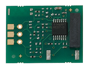
The Polar Heart Rate Receiver is designed to receive heart beat signals from compatible Polar heart rate sensors. Together, the sensor and receiver provides a low-cost and convenient heart rate monitoring system that can be connected to most any microcontroller. Example uses include home exercise and sports training.
The Heart Rate Receiver is a stand-alone module, with on-board connections for power (3.3 V to 5 V), ground, and signal. It wirelessly interfaces to a compatible Polar coded or uncoded sensor transmitter, such as the Polar T34 Non-Coded Transmitter.
Range between transmitter and receiver is intentionally limited to about 3 to 4 feet, so that multiple heart rate monitors can be used within the same general area.
Parts List
- Polar Heart Rate Receiver
- Polar T34 Non-Coded Heart Rate Transmitter
- BASIC Stamp HomeWork Board, Propeller QuickStart, or Arduino Uno microcontroller
- 22 gauge solid conductor hookup wire
Basic Wiring

- Power requirements: 3.3 to 5.5 VDC , 200 μA (at 5 VDC)
- Communication: 5 kHz coded or uncoded pulses
- Dimensions: 0.75 in x 1 in
- Signal output: 15 ms TTL level high (+V) pulse on received heart beat
- Maximum signal distance: 100-125 centimeters (3-4 feet)
To make it easy to connect the Heart Rate Receiver to a breadboard or other circuit, solder a three-pin male header connector (Parallax #451-00303, not included) to the pads on the side of the module. As shown in the diagrams in this KickStart, the long portion of the header pins is on the side of the board with the foam tape. With this arrangement, the Heart Rate Receiver module can plug directly into a solderless breadboard, or to another circuit via a three-wire extension, such as Parallax #800-00080.
Program KickStarts
Each of the example programs use the serial monitor or debugging window to indicate when a heartbeat signal is received. Upon registering a heartbeat from the sensor transmitter, the receiver produces a momentary HIGH output on the Signal pin. This HIGH state is detected in the program, and the word “Beat” is displayed in the serial window.
Important! A signal is received only if there is a compatible heart rate sensor transmitter within operating distance (typically four feet or less). The sensor must be worn in accordance with the instructions packaged with it.
If a signal is not received, or if false readings occur, check for proper placement of both the sensor transmitter and body strap. If your transmitter uses a replaceable battery, verify that the battery in the sensor is fresh.
BASIC Stamp 2 HomeWork Board

Download BASIC Stamp 2 code for the Polar Heart Rate Monitor
' {$STAMP BS2}
' {$PBASIC 2.5}

'Definitions
HR_RX       PIN 0
oldSample   VAR Bit
sample      VAR Bit

'Set signal pin to input
INPUT HR_RX


DEBUG CLS, "Waiting for heart beat...", CR

'Wait until a heart beat is detected
DO UNTIL HR_RX
LOOP

DEBUG "Heart beat detected!", CR

'Main Loop
DO

  sample = HR_RX       'Store signal output
  IF sample AND oldSample <> sample THEN DEBUG "Beat", CR
  oldSample = sample   'Store last signal received

LOOP
When this program is run, the BASIC Stamp Debug Terminal will automatically open.
Propeller BOE and Propeller QuickStart

Propeller BOE Wiring Diagram

Propeller QuickStart Wiring Diagram
Download Propeller Spin code for the Polar Heart Rate Monitor
OBJ
  pst:  "Parallax Serial Terminal"


CON

  _clkmode = xtal1 + pll16x
  _xinfreq = 5_000_000

  'Pin definitions
  HR_RX    = 0

VAR

  'Variable Definitions
  byte  oldSample
  byte  sample

PUB go

  'Start the Parallax Serial Terminal
  pst.start(115_200)
  pst.clear

  'Set signal pin to input
  dira[HR_RX]~

  pst.str(string("Waiting for heart beat...", pst#NL))

  'Wait until a heart beat is detected
  repeat until ina[HR_RX]

  pst.str(string("Heart beat detected!", pst#NL))

  'Main Loop
  repeat

    sample := ina[HR_RX]    'Store signal output
    if sample and oldSample <> sample
      pst.str(string("Beat", pst#NL))

    oldSample := sample     'Store last signal received
This program uses the Parallax Serial Terminal object library, which is included with the Propeller Tool software download.
To view the results of the demonstration, after uploading is complete run the Parallax Serial Terminal from the Run menu, or press F12. Momentarily depress the Reset button on the Propeller QuickStart board to restart the program.
Arduino Uno

Download Arduino 1.0 Code for the Polar Heart Rate Monitor
//Definitions
const int HR_RX = 7;
byte oldSample, sample;

void setup() {
  Serial.begin(9600);
  pinMode (HR_RX, INPUT);  //Signal pin to input

  Serial.println("Waiting for heart beat...");

  //Wait until a heart beat is detected
  while (!digitalRead(HR_RX)) {};
  Serial.println ("Heart beat detected!");

}

void loop() {

  sample = digitalRead(HR_RX);  //Store signal output
  if (sample && (oldSample != sample)) {
    Serial.println("Beat");
  }
  oldSample = sample;           //Store last signal received

}
To view the results of the demonstration, after uploading is complete click the Serial Monitor icon in the Arduino IDE. This displays the Serial Monitor window. Momentarily depress the Reset button on the Arduino board to restart the sketch.