The ELEV-8 v3 is a workhorse quadcopter – it’s sturdy, reliable, and most importantly, hackable! Adding servos gives your ELEV-8 v3 the ability to do any number of tasks. This tutorial contains beginner, intermediate, and advanced elements that will help you use additional servos to modify your ELEV-8 v3. Although this tutorial will use specific hardware, many of the concepts will apply to other receivers, transmitters, and servos.
It is possible to complete this tutorial by simply plugging in servos to the flight controller and making changes to the code. If you choose to add servos more permanently to your ELEV-8 v3, you will need to take special care that:
The easiest way to add a servo to your ELEV-8 v3 quadcopter is to drive it with a spare channel on the ELEV-8 v3’s receiver.
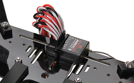
R/C receivers, such as the Spektrum AR610 6-Channel or the Spektrum AR8000 8-Channel receivers output a PWM (pulse-width modulated) signal that tell standard servos what position they should turn to and hold:

R/C servos are made to turn in a limited arc, no more than about 180°. You set the precise position of the output shaft of the servo motor by using the timing signal; this signal is provided by a microcontroller. Once the signal is applied, the motor moves to that position and stays there.
The control signal for a servo is a stream of pulses. The exact duration of these pulses, in fractions of a second, is what determines the position of the servo. Each pulse is nominally from 1000 to 2000 microseconds (μs) in duration — one microsecond is one millionth of a second. The pulses repeat about 50 times each second.
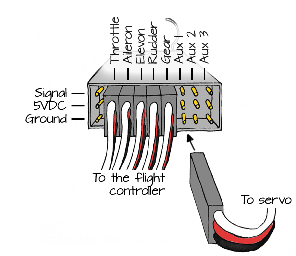
Your ELEV-8 v3 quadcopter needs 5 channels to fly: throttle, rudder, elevators, ailerons and gear/mode. If your transmitter and receiver have additional channels available, you can use a spare channel to drive a servo.
or this:
If a cable is already connecting the channel labeled Aux 1 on your receiver to your flight controller, it is safe to remove it – it is not critical for flight using the standard firmware.
STOP!
REMOVE THE PROPELLERS FROM YOUR QUADCOPTER BEFORE PROCEEDING!
Although this works well if your transmitter has knob, not all transmitters do. If you had to use a switch, you have noticed that you can only move the servo to 2 or 3 different positions.
By connecting that spare channel back up to the flight controller, you can modify the firmware on the flight controller to drive the servo in nearly any manner you choose.
A complete, tested, configured ELEV-8 v3 (Parallax Item #80300 or Item #80330) that has a receiver with at least 6 channels, such as:
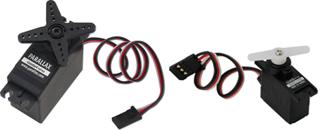
At least one R/C servo, such as:
If you wish to mount your servos to the bottom chassis plate of your ELEV-8 v3, you will need hardware and/or adhesive, such as:
Servos that are under load—lifting a weight or pulling against something—will need more current than if they are just moving freely. If you are designing an ELEV-8 add-on that will put a load on the servos, they will need more current than the Flight Controller can supply. So, you would also need to build a separate power supply for your servos.
Connecting a servo to the Parallax Flight Controller on your ELEV-8 v3 quadcopter, and editing the firmware, gives you more control of the servo.
The original Parallax Flight Controller firmware only generates servo pulses ranging from 1000 μs to 2000 μs (1.0 ms to 2.0 ms) wide. Many servos operate over a wider range, ~700 μs to ~2300 μs. So, the original Parallax Flight Controller firmware will only drive the servo through a portion of its full range:
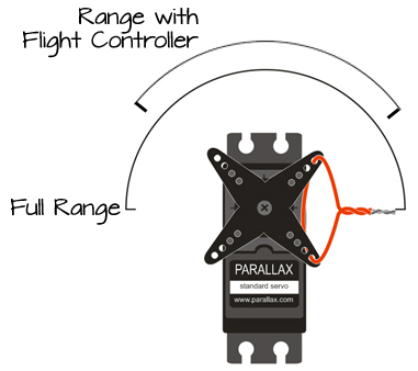
This is important to note if the servo you are driving with the Parallax Flight Controller is part of a mechanism attached to your ELEV-8 v3.
If you haven’t done so already, follow the directions here (/courses/elev-8-v3-quadcopter-assembly-guide/step-22-install-software) to open the ELEV-8 v3 firmware using SimpleIDE. Make sure you understand how to upload firmware to your ELEV-8 v3. This project was tested with firmware version 1.0.2 and 1.0.3.
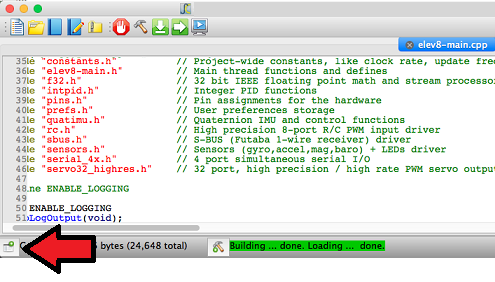
A list of files will appear on the left side of the window.
static long LEDModeColor;
static int servoPosition = 8000; // create a variable to store the servos position, also tells servo where to start
  Servo32_Init( 400 );
  for( int i=0; i<4; i++ ) {
    Servo32_AddFastPin( MotorPin[i] );
    Servo32_Set( MotorPin[i], Prefs.MinThrottle );
  }

  Servo32_Start();
Servo32_AddSlowPin( PIN_MOTOR_AUX1 );     // Add a standard servo on PIN_MOTOR_AUX1
Servo32_Set( PIN_MOTOR_AUX1, servoPosition );      // Set the starting position
S4_Define_Port(3, 115200, PIN_MOTOR_AUX2, TXBuf4, sizeof(TXBuf4), 32, RXBuf4, sizeof(RXBuf4));
S4_Define_Port(3, 115200, 32, TXBuf4, sizeof(TXBuf4), 32, RXBuf4, sizeof(RXBuf4));
UpdateFlightLEDColor();
if( Radio.Aux1 < -512 ) servoPosition = servoPosition - 12;  // if the switch/knob is low/down, turn counterclockwise
if( Radio.Aux1 >  512 ) servoPosition = servoPosition + 12;  // if the switch/knob is high/up, turn clockwise

servoPosition = clamp( servoPosition, 8000, 16000 );         // don't let the variable go outside of the 8000 to 16000 range!!
Servo32_Set( PIN_MOTOR_AUX1, servoPosition );                // set the servo position
DO NOT CONNECT YOUR ELEV-8’s Battery. Make sure the propellers have been removed from your ELEV-8 quadcopter before continuing.
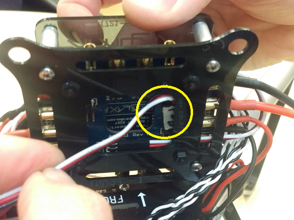
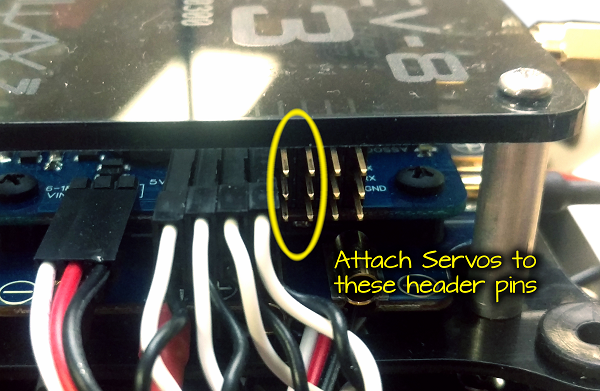
Once you have edited the firmware to support adding a servo to the Flight Controller, you are ready to plug in the servo.
MAKE SURE the propellers have been removed from your ELEV-8 v3 and the battery is unplugged before proceeding!
To download the template file (AXD, DXF, and PDF) for the drop-rig mechanism, click here:
The Parallax Flight Controller’s firmware contains a servo driver that generates the pulses necessary to drive the servo. Although the driver has a high resolution and it supports high update rates, its range is limited.
You may have noticed the following code in the elev8-main.cpp file:
  Servo32_Init( 400 );
  for( int i=0; i<4; i++ ) {
    Servo32_AddFastPin( MotorPin[i] );
    Servo32_Set( MotorPin[i], Prefs.MinThrottle );
  }
  Servo32_Start();
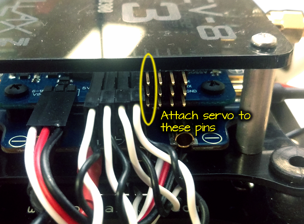
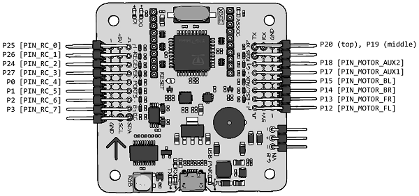
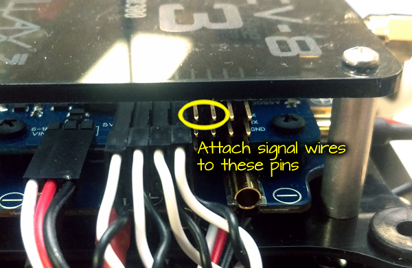
This code tells the servo drivers to create high-speed servo instances on each of the first 4 pins on the right side of the Flight Controller (labeled ESC/AUX). This is where the ESCs that drive the motors for flight are attached. They use the same signals as servos, except that their pulses are sent 400 times per second instead of 50 times per second for standard servos. The drawing below shows the pin and how they are referenced in the firmware:
The code you added sets up a standard (“slow”) servo instance on the next pin header, where you plugged in your additional servo:
  Servo32_AddSlowPin( PIN_MOTOR_AUX1 );
  Servo32_Set( PIN_MOTOR_AUX1, servoPosition );
The next line you added tells the servo to start sending pulses that are exactly 1000 μs (1.0 ms) wide. You may have noticed that the variable (servoPosition) that tells the servo driver to send 1000 μs pulses contains the number 8000 – this is because the servo driver has a resolution of ⅛th of a microsecond. 8 times 1000 = 8000.
Since the driver supports an output range from 1000 μs to 2000 μs, you can give it any value from 8000 to 16000.
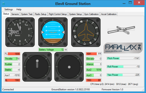
The next lines of code read the value send by the receiver to the Flight Controller. These values range from -1024 to +1024. In fact, you can see these values next to the sticks at the bottom of the window when your Flight Controller is connected to the Parallax GroundStation software on your computer:
  if( Radio.Aux1 > 512  ) servoPosition = servoPosition + 12;
  if( Radio.Aux1 < -512 ) servoPosition = servoPosition - 12;
The next line of code ensures that you don’t send any number lower than 8000 or higher than 16000 to the servo driver. In fact, sending a number outside of that range will cause the servo driver to lock up, and if that happens in flight, your ELEV-8 v3 will likely crash:
servoPosition = clamp( servoPosition , 8000, 16000);
And finally, the servo is set to the position specified by servoPosition:
Servo32_Set( PIN_MOTOR_AUX1, servoPosition);
Always use the clamp() function to make sure you do not send values outside of the 8000 to 16000 range to the servo driver!
To make the servo travel faster, you simply need to change how much is added or subtracted during each cycle. If you use servoPosition = servoPosition + 24, the servo will move twice as fast.
Use a different channel to drive the servo.
Radio.Elev, Radio.Aile and Radio.Aux2 are also available, and each has a range from -1024 to +1024.
Instead of using the transmitter to tell the servo to go clockwise or go counter clockwise, you can set it’s position directly.
  if( Radio.Aux1 > 512  ) servoPosition = servoPosition + 12;
  if( Radio.Aux1 < -512 ) servoPosition = servoPosition - 12;
servoPosition = 12000 + ( Radio.Aux1 * 4 );
The code above multiplies Radio.Aux by 4, so it’s range goes from -4096 to +4096. It then adds it to 12000, meaning that the range goes from 7904 to 16096. It is then run through the clamp() function to make sure that it stays between 8000 and 16000.
DO NOT Fly your ELEV-8 v3 with modified firmware or hardware until you have read how to test it safely on the last page of this tutorial!
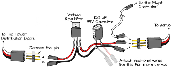
If you plan to attach a servo to your ELEV-8 v3 and use it in flight, it is a good idea to give it its own power supply. With a few components and a little soldering, it is easy to build a power supply for your additional servos.
DO NOT PROCEED unless the propellers and battery have been removed from your ELEV-8 v3!
If you hear any popping or hissing, or smell something hot or smoke, immediately disconnect the battery!
DO NOT FLY Your ELEV-8 v3 after modifying the hardware or firmware until you have completed the safety testing on the last page of this tutorial!
Although it is useful to use a spare channel on your transmitter to drive a servo, you can drive a servo using other variables in the Flight Controller’s firmware instead. For instance, a useful application for servos is a sensor gimbal. You may have a sensor that needs to stay level or that always points straight down. Since the Flight Controller always knows its orientation, you can use its computed pitch and roll to drive servos in use as a gimbal.
The latest version of the Firmware available on GitHib includes code for computing Pitch and Roll – if you download your firmware from GitHub after April 5, 2016, you can skip to the section titled “Edit the elev8-main.cpp file” below.
A list of files will appear on the left side of the window.
//Add containers for Pitch and Roll measurements
int QuatIMU_GetPitch(void);
int QuatIMU_GetRoll(void);
    //Add variables for Pitch and Roll and associated scaling constants
    Pitch,
    Roll,
    const_outAngleScale,
    const_outNegAngleScale,
  //Define the scaling constants
  IMU_VARS[const_outAngleScale]     =    65536.0f / PI;
  IMU_VARS[const_outNegAngleScale]  =   -65536.0f / PI;
//Create functions to retrieve the calculated Pitch and Roll Measurements
int QuatIMU_GetPitch(void) {
  return INT_VARS[Pitch];
}

int QuatIMU_GetRoll(void) {
  return INT_VARS[Roll];
}
//Calculate the Pitch and Roll
        F32_opASinCos, m12,  const_1, temp,
        F32_opMul, temp,  const_outAngleScale, temp,
        F32_opTruncRound, temp,  const_0, Pitch,

        F32_opASinCos, m10,  const_1, temp,
        F32_opMul, temp,  const_outNegAngleScale, temp,
        F32_opTruncRound, temp,  const_0, Roll,
  Servo32_AddSlowPin( PIN_MOTOR_AUX1 );  // Add a servo to this pin for Pitch
  Servo32_AddSlowPin( PIN_MOTOR_AUX2 );  // Add a servo to this pin for Roll

  Servo32_Set( PIN_MOTOR_AUX1, 12000 );  // Set this servo to center (1.5 ms)
  Servo32_Set( PIN_MOTOR_AUX2, 12000 );  // Set this servo to center (1.5 ms)
  int servoRoll  = QuatIMU_GetRoll()  / 5;  // divide by 5 to match the servo's movement to the actual roll, may need to adjust
  int servoPitch = QuatIMU_GetPitch() / 5;  // divide by 5 to match the servo's movement to the actual pitch, may need to adjust;

  servoPitch = servoPitch + ( Radio.Aux1 << 1);  // Add the Aux1 channel to the pitch to control the gimbal's tilt.
                                                 // You can delete this line if you don't want to do this

  servoRoll  = clamp( (12000 - servoRoll),  8000, 16000 );  // Make sure the Roll and Pitch don't go out of range
  servoPitch = clamp( (12000 - servoPitch), 8000, 16000 );

  Servo32_Set( PIN_MOTOR_AUX1, servoRoll  );  // Send the values to the servos
  Servo32_Set( PIN_MOTOR_AUX2, servoPitch );
DO NOT CONNECT YOUR ELEV-8’s Battery yet! Make sure the propellers have been removed from your ELEV-8 quadcopter before continuing!
DO NOT Fly your ELEV-8 v3 with attached servos unless they are connected through a separate power supply!
DO NOT Fly your ELEV-8 v3 with modified firmware or hardware until you have followed the procedure to test it safely on the last page of this tutorial!
Now that you have modified the hardware and/or firmware for the ELEV-8 v3, it is necessary to test its functionality to make sure it is safe to fly. Yes, do this every time you made hardware and/or firmware modifications!
DO NOT SKIP THIS PROCEDURE! Flying with untested firmware is dangerous and can cause severe injury or property damage or loss.
If you have not done so already, REMOVE YOUR PROPELLERS before proceeding!
If your ELEV-8 v3 fails to pass any of the steps below, STOP – disconnect the ELEV-8 v3’s battery and return to prior steps to begin troubleshooting the problem.
Pay close attention to the RGB LED on the Flight Controller. During this process, it should continue to flash/alternate colors. Except during power-up, arming and disarming, if the LED stops flashing, there is a problem with your code and it is not safe to fly.
The Propeller microcontroller on the Flight Controller has a system clock that takes approximately 53 seconds to roll back over to zero and start again. Testing for 90 seconds ensures that the rollover will not cause a lock-up.
If your ELEV-8 v3 passed all of the above tests, it should be safe to re-install the propeller blades when you are ready to fly.
For your first flight with modified firware and hardware, follow all safety precautions.
Fly gently, close to the ground, and away from any people, objects, or structures until you are confident that your ELEV-8 v3 is performing normally.