This project demonstrates two important functionalities:
By organizing your data in EEPROM you can create and easily access a database of records. While the example uses names of our presidents, it could be used as a basis to identify machines in a makerspace, inventory types or asset tracking. Humans more readily relate descriptions or names to an item than a number.
The FLiP module was chosen due to low cost and small size, but this project can also be done with the Propeller Activity Board WX—which may be a better choice if you want to quickly add Internet of Things (IoT) connectivity with the WX Module.
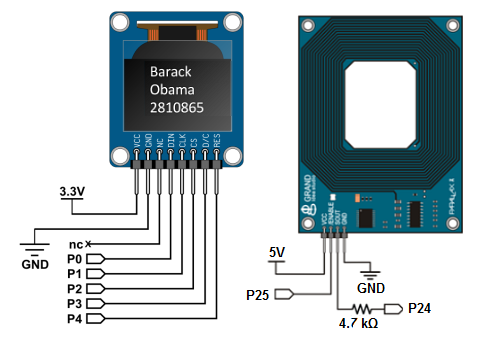
If using an Activity Board instead of a FL!P, follow the wiring schematics and make sure to choose different I/O pins for the RFID reader connections. Correct your code to use the pins you selected. If you need an example, take a look at the wiring diagram from our C-language RFID Reader tutorial.
First, you need to load the EEPROM fonts into your FLiP. Simply drag this block onto your Blockly workspace and download to the FLiP’s EEPROM.
Next, we’ll determine the numbers on your various RFID tags. Each tag has a seven-digit integer number (plus a few other numbers that represent the vendor ID, but we’re not using them in Blockly). The FLiP – RFID Reader for Numbers Blockly program can be used to read the tags and write their numbers to your OLED. Download it here:
Project4261-RFID-Read-Numbers.svg
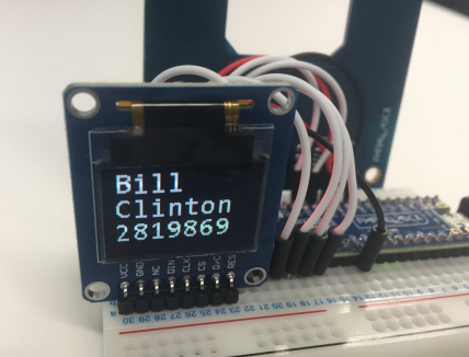
Scan your tags and write the numbers you see from the OLED. The tag numbers I recorded were 2819869, 6618834, 2809834, 2810865 and 2841692. Yours will be different.
The next step would be to identify the names you’ll associate with the RFID tag numbers. Each RFID tag number is four bytes. Four bytes is 32 bits – or a word variable – which stores a number between zero and 2,147,483,647.
This example will associate the RFID tag number with the names of five recent presidents. Since the OLED’s maximum number of characters (using medium sans font) is eight we’ll use that as a limitation. The first and last name of recent presidents are each less than eight characters.
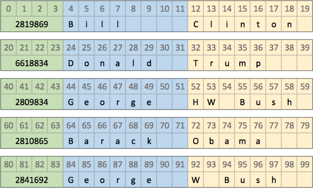
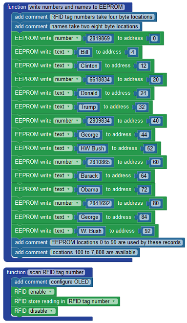
When reading from memory it’s a good idea to arrange your data consistently. For example, 20 bytes can store the RFID tag number, first name, and last name of the president in the following format:
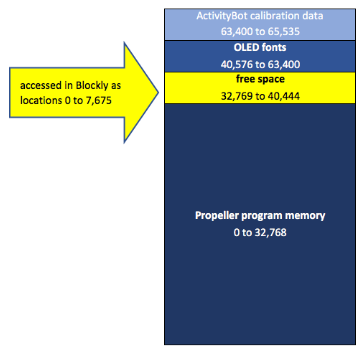
It’s helpful to know exactly where this data is stored in the Propeller’s EEPROM, too. The FLiP uses a 64K byte EEPROM – with the lower half (32K bytes) being used for your program memory. This leaves the upper 32K bytes of space for storing other data. However, the Blockly creators allocated sections of this upper half of memory for the ActivityBot encoder calibration data and OLED fonts. This left locations 32,769 to 40,444 (7,675 bytes) for data of your choice.
Using our example with the RFID tag numbers and president names, 7,675 bytes could store 383 records (7,675 bytes divided by 20 bytes per record). This may be plenty of space for storing the presidential records, but imagine keeping track of weather data or inventory. For those projects it would be better to use the SD Card blocks. A look at how this 64K EEPROM memory is organized:
Blockly also conveniently recalculates the memory locations so you can write to location 32,768 as location 0. A quick look at the C code equivalent shows how this is accomplished for you by adding 32,768 to your memory location:
void write_numbers_and_names_to_EEPROM()

{

   // RFID tag numbers take four byte locations

   // names take two eight byte locations

   ee_putInt(2819869, (32768 + constrain(0, 0, 7675)));

   ee_putStr(("Bill"), (strlen(("Bill")) + 1), (32768 + constrain(4, 0, 7675)));

   ee_putStr(("Clinton"), (strlen(("Clinton")) + 1), (32768 + constrain(12, 0, 7675)));
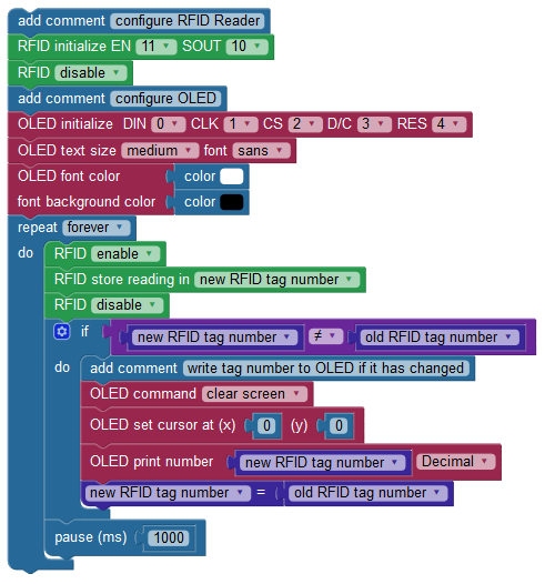
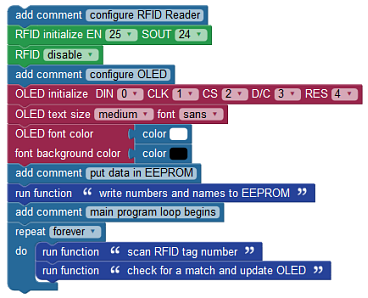
The FLiP – RFID Reader with EEPROM Names program below is the complete Blockly example shown in the video on the first page of this project. The program has three main functions which are quite easy to understand. Download it here:
Project4260-FLiP-RFID-EEPROM-Names.svg
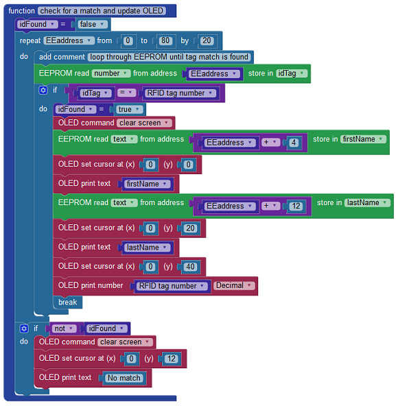
The “check for a match and update OLED” function is where the scanned RFID tag number is read and compared to a RFID tag number stored in EEPROM at 20 byte increments. If a match is found, the first and last names are also retrieved. This is done by incrementing an EEPROM location pointer by 4 and 12 bytes, storing the names in firstName and lastName, and writing them to the OLED.
