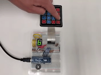
Keypads and displays provide a human interface to your applications. This project consists of a seven-segment display and 4×4 matrix keypad connected to a Propeller FLiP Module. When a keypad button is pressed the value or character will be shown on the seven-segment display and a piezo speaker will play a confirmation tone. This program provides a template which can be expanded for other purposes, including setting motor speed with the touch keypad, and positioning a servo to ten different locations.
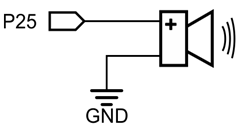
To make this project work on an Activity Board, you will need to leave off the piezospeaker and be careful not to let resistor leads touch. Breadboard space will be limited.
This 4×4 matrix keypad circuitry is based on two other examples: Read a 4×4 Matrix Keypad (from Propeller C – Simple Devices), and the BlocklyProp Propeller Reference for 4×4 matrix keypad (Sensor > 4 x 4 Keypad). The seven-segment display circuitry is similar to the Propeller C – Simple Circuits Seven-Segment Display tutorial; however, wiring the 4×4 keypad and a seven-segment display together requires some changes to the schematic so the two systems can be viewed right-side up on your breadboard.
Build the circuits shown below, following the wiring diagram and schematics.
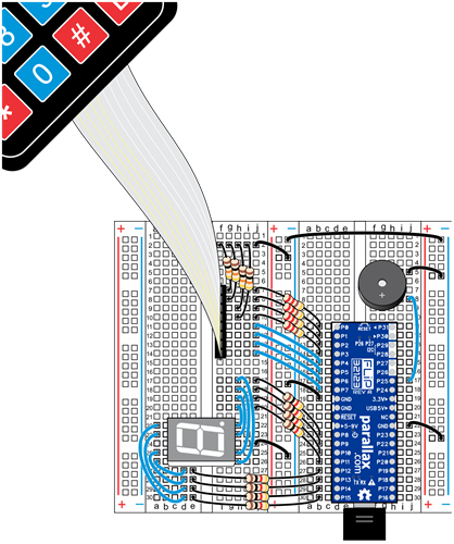
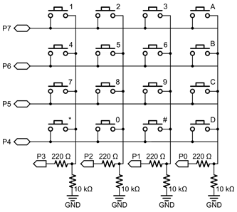
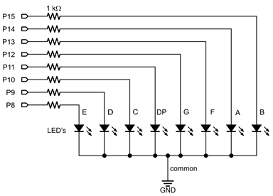
Double-check to make sure the correct resistors are used. 1 kΩ resistors for the seven-segment display, 10 kΩ resistors for the grounded pins on the 4×4 matrix keypad, and 220 Ω resistors for the P0-P3 I/O pin keypad connections.
The best way to program this project is in three pieces:
Project8624-4×4-Matrix-Keypad-Test.svg
Next, test the seven-segment display by loading the Blockly code for the Seven-Segment Display Test:
Project8621-Seven-Segment-Test.svg
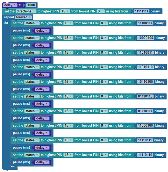
This will cycle through numbers 0-9 in an endless loop.
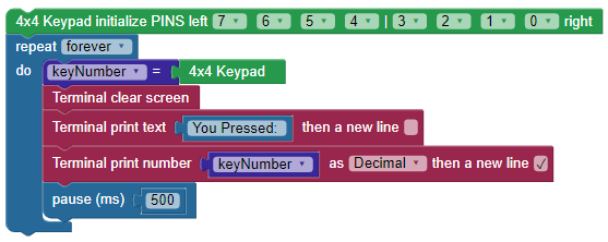
If the 4×4 matrix keypad and seven-segment display codes worked successfully, then you’re ready to run the Blockly code for the 4×4 Matrix Keypad with Seven-Segment Display (shown in full below):
Project8331-4×4-Keypad-7-Seg-Display.svg

First, let’s look at how it actually works. Then, we’ll give some suggestions for how you could make this project better suit your needs.
The program initializes the 4×4 matrix keypad using the FLiP module’s first eight pins (P0-P8). It also sets the states of the seven-segment display pins to outputs, while attaching a binary value of 11111111. Next, the code enters an infinite repeat loop containing a variable called keyNumber that gets updated every pass through the loop. Three individual functions are also run every time through the loop: terminalPrint, checkKey, and beep.
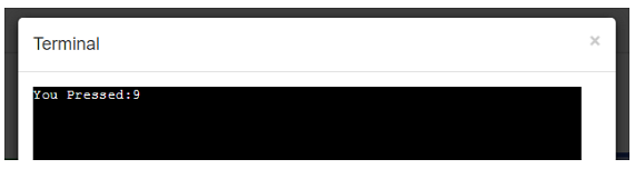
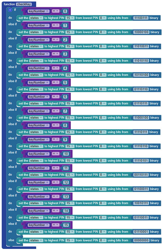
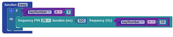
The terminal displays the value from the keypad as -1 if nothing is pressed, or a value ranging from 0-15 if being pressed (depending on which button you are pressing). The checkKey function receives a decimal value from the keypad then set the states of all pins from 8 to 15 to the corresponding binary value. If nothing is pressed, all pins are turned off by making them low (a binary value of 00000000). The “beep” function makes a sound for a half second every time a button is pressed when the value of “keyNumber” greater than or equal to 0.
Make some modifications to the project to make it work more effectively. Try the following:
