]
Timers are extremely useful in everyday life. We use them to cook, play games, and sometimes during tests. This activity will show you how to build your own 1–9 minute timer using only parts included in the BASIC Stamp Activity Kit (#90005).
If you are new to the BASIC Stamp microcontroller or to programming, it would be a good idea to review the following before continuing:
This activity can be completed solely with the parts included in the BASIC Stamp Activity Kit (#90005) or the RadioShack What’s a Microcontroller BASIC Stamp Kit. Below is a listing of all parts required for this activity:
Source code for Build Your Own Mini Timer
Not only does this activity provide another useful application for your WAM Kit, but it is also a great lesson on optimizing your breadboard real estate. There are a lot of components to fit onto the board, so we need to make the most of the space available. Figure 1 shows the schematic for this mini timer.
If you have difficulties assembling the timer, check this Parallax forum thread for more help.
Figure 1 – Mini Timer Schematic

Once everything is wired, it’s important to check that everything is wired correctly. The program below will test each aspect of the circuit in one shot. Make sure you have the full source code for this project from the previous page, then run TestCircuit.bs2 and verify that the following occurs:
' TestCircuit.bs2
' Test each electrical component to be sure things were wired correctly.

' {$STAMP BS2}
' {$PBASIC 2.5}

time     VAR    Word                      ' Variable space for decay time

OUTH = %00000000                          ' Clear LED display
DIRH = %11111111                          ' Set pins 8-15 to outputs

FREQOUT 7, 100, 3500                      ' Test speaker
PAUSE 100
FREQOUT 7, 100, 3500

OUTH = %11100111                          ' 0
PAUSE 500
OUTH = %10000100                          ' 1
PAUSE 500
OUTH = %11010011                          ' 2
PAUSE 500
OUTH = %11010110                          ' 3
PAUSE 500
OUTH = %10110100                          ' 4
PAUSE 500
OUTH = %01110110                          ' 5
PAUSE 500
OUTH = %01110111                          ' 6
PAUSE 500
OUTH = %11000100                          ' 7
PAUSE 500
OUTH = %11110111                          ' 8
PAUSE 500
OUTH = %11110110                          ' 9

DO
  HIGH 0                                  ' Test potentiometer
  PAUSE 100
  RCTIME 0, 1, time
  DEBUG HOME, "time = ", DEC5 time, CR    ' Display decay time

  DEBUG ? IN3                             ' Display PB states
LOOP
While running this program, one important thing to check is the range of decay times for the potentiometer, which will be used to change the display of the 7-Segment LED from 0–9. Using this range, we can calculate the decay time interval for each minute, ensuring that the minutes complete a full cycle with the potentiometer. Each potentiometer can vary, so for the most accurate results it is very important that you check the range for your potentiometer.
For example, say your potentiometer range was 1–594. Since we want to display 10 total digits (0–9), we can divide 594 by 10 to get a decay time increment of 59.4. This means we’ll want the number displayed on the 7-Segment LED to change whenever the decay time increases by 59:
|
Minute |
0 |
1 |
2 |
3 |
4 |
5 |
6 |
7 |
8 |
9 |
|
Decay Time Value |
1 |
60 |
119 |
178 |
237 |
296 |
355 |
414 |
473 |
532 |
This brings us to our next test program, TestNumbers.bs2. Run this program and verify that the 7-Segment LED displays the numbers 0–9 as the user rotates the potentiometer.
' TestNumbers.bs2
' Test that the numbers increase from 1-9 when turning the pot.

' {$STAMP BS2}
' {$PBASIC 2.5}

index    VAR    Nib
time     VAR    Word

OUTH = %00000000                ' Clear LED display
DIRH = %11111111                ' Set pins 8-15 to outputs

DO
  HIGH 0
  PAUSE 100
  RCTIME 0, 1, time

  LOOKDOWN time, <= [ 1, 60, 119, 178, 237, 296, 355, 414,
                     473, 532 ], index

  LOOKUP index, [ %11100111, %10000100, %11010011, %11010110,
                  %10110100, %01110110, %01110111, %11000100,
                  %11110111, %11110110 ], OUTH
LOOP
This program uses the LOOKUP and LOOKDOWN commands to display digits on the 7‑Segment LED. First, the program takes an RCTIME measurement and stores it in the variable time.
HIGH 0
PAUSE 100
RCTIME 0, 1, time
The LOOKDOWN table then uses the value stored in time to determine which number in the list time is smaller than or equal to. It then loads that number’s entry number (which is 0–9 in this case) into the variable index.
LOOKDOWN time, <= [ 1, 60, 119, 178, 237, 296, 355, 414,
                   473, 532 ], index
Lastly, the LOOKUP table uses the value in index to display the proper number on the 7‑Segment LED. The corresponding binary value is then loaded into the OUTH variable.
LOOKUP index, [ %11100111, %10000100, %11010011, %11010110,
                %10110100, %01110110, %01110111, %11000100,
                %11110111, %11110110 ], OUTH
Figure 2 – The Timer Circuit
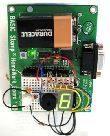
Once the circuit has been tested and the numbers 0–9 are displayed on the 7-Segment LED, there’s just a bit more to add to the code in order to complete the timer.
' -----[ Title ]-------------------------------------------------------------
' MiniTimer.bs2
' Simple timer to time 1-9 minutes based on user input.
' {$STAMP BS2}                               ' Stamp directive -> BS2
' {$PBASIC 2.5}                              ' PBASIC directive -> v2.5

' -----[ Variables ]---------------------------------------------------------

index        VAR    Nib         ' Variable space for LOOKUP/LOOKDOWN
time         VAR    Word        ' Decay time of potentiometer
totalSecs    VAR    Word        ' Total number of minutes entered by user
duration     VAR    Word        ' Variable space for FOR...NEXT loop
frequency    VAR    Word        ' Frequency

' -----[ Initialization ]----------------------------------------------------

OUTH = %00000000                ' Clear LED display
DIRH = %11111111                ' Set pins 8-15 to outputs

FREQOUT 7, 100, 3500            ' Program startup sound
PAUSE 100
FREQOUT 7, 100, 3500

' -----[ Main Routine ]------------------------------------------------------

DO
  HIGH 0                       ' Get decay time measurements
  PAUSE 100
  RCTIME 0, 1, time

  LOOKDOWN time, <= [ 1, 60, 119, 178, 237, 296,     ' Compare decay time to
                     355, 414, 473, 532], index      ' pre-determined values

  LOOKUP index, [ %11100111, %10000100, %11010011,   ' Display 0-9 based on
                  %11010110, %10110100, %01110110,   ' the value in index
                  %01110111, %11000100, %11110111,
                  %11110110 ], OUTH
LOOP UNTIL (IN3 = 1)           ' Loop until button pressed

totalSecs = index * 60         ' Calculate number of 1s increments needed to
                               ' match number of minutes selected by the user

FREQOUT 7, 500, 3000           ' Tone to note start of countdown

FOR duration = totalSecs TO 0
  PAUSE 990                                          ' Wait 1 second

  LOOKDOWN duration, <= [  0,  60, 120, 180,         ' Compare value in
                         240, 300, 360, 420,         ' duration to
                         480, 540], index            ' number of seconds
  LOOKUP index, [ %11100111, %10000100, %11010011,   ' Display 0-9 based on
                  %11010110, %10110100, %01110110,   ' the value in index
                  %01110111, %11000100, %11110111,
                  %11110110 ], OUTH
NEXT

FOR duration = 15 TO 1                               ' Play "times up" tone
  FOR frequency = 3000 TO 3500 STEP 20
    FREQOUT 7, duration, frequency
  NEXT
  FOR frequency = 2000 TO 2500 STEP 10
    FREQOUT 7, duration, frequency
  NEXT
NEXT
The first part of the program completes the same tasks as TestNumbers.bs2. However, instead of displaying the numbers indefinitely, the program waits for the user to press the button and then starts the timer. Before executing the timer loop, we need to convert the number of minutes for the timer to seconds. This allows us to use a FOR…NEXT loop and a PAUSE command to easily count down each minute.
You may also notice that the program only pauses for 990 ms instead of the expected 1000 ms. This is because when comparing the results of this timer with a stopwatch, it was found that the LOOKUP and LOOKDOWN statements take about 10 ms to execute. So really, the approximate pause time of the FOR…NEXT loop is 1000 ms.
Finally, additional LOOKUP and LOOKDOWN commands show the user how many minutes are left on the timer by comparing the value in the variable duration to a table of second values.
FOR duration = totalSecs TO 0
  PAUSE 990

  LOOKDOWN duration, <= [  0,  60, 120, 180,
                         240, 300, 360, 420,
                         480, 540], index

  LOOKUP index, [ %11100111, %10000100, %11010011,
                  %11010110, %10110100, %01110110,
                  %01110111, %11000100, %11110111,
                  %11110110 ], OUTH
NEXT
To finish, the piezospeaker emits a unique series of tones to let the user know the timer is up. These tones can be customized to whatever you would like, so get creative! If you need inspiration, check out Chapter 8 in What’s a Microcontroller?
FOR duration = 15 TO 1
  FOR frequency = 3000 TO 3500 STEP 20
    FREQOUT 7, duration, frequency
  NEXT
  FOR frequency = 2000 TO 2500 STEP 10
    FREQOUT 7, duration, frequency
  NEXT