When an accelerometer is mounted on the Boe-Bot robot, it can be programmed to seek out hilltops or valleys. It can also be programmed to detect when the hill it’s trying to climb is too ambitious and seek out another route. Instead of an autonomous roaming aid for the Boe-Bot, an accelerometer can be a useful tool in a tilt radio controller. The great thing about the Boe-Bot is that it can also be directed by a remote controller, but use the intelligence you program into it to decide whether or not to follow the instructions it’s receiving.
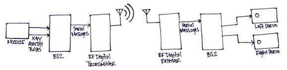
This activity uses a single serial RF channel to transmit the x-axis and y-axis tilt information from your handheld RF tilt controller to the Boe-Bot. The BASIC Stamp module in the RF tilt controller captures the tilt pulses from the MX2125, and stores them in its RAM. It then sends the serial version of these values to the transmitter in the RF Transceiver it’s connected to, which in turn modulates and broadcasts the serial messages. If the receiver on the Boe-Bot’s RF Transceiver is in range, it receives and demodulates the message, and sends the reproduced serial message to the Boe-Bot’s BASIC Stamp. When the BASIC Stamp gets the x-axis and y‑axis tilt measurements, it can then use them to make navigation decisions and send control pulses to its servos. The block diagram of this process is below in Figure 1:
Figure 1 – Block Diagram
This project contains advanced topics, not intended for Boe-Bot beginners. Before continuing, it is highly recommended you complete the following tasks in order to gain a better understanding on how this application works:
(1) Fully assembled and tested Boe-Bot® Robot (#28132)
The parts below are included in the Boe-Bot Robot kit:
(1) Piezospeaker (#900-00001)
(4) 220 Ω Resistors (#150-02210)
(1) HomeWork Board with BASIC Stamp 2 (#28158)
The BASIC Stamp 2 Board of Education (#28103) or the RadioShack What’s a Microcontroller BASIC Stamp Kit is also suitable for this activity
(1) Memsic 2125 Dual-axis Accelerometer (#28017)
(2) 433 MHz RF Transceivers (#27982)
Using wires instead of RF
So long as your wire harness is in the neighborhood of 3 ft (or 1 m), you can replace the transmitter/receiver/transceiver with 2 wires. The first wire has to connect the Vss terminals on both boards. The second wire connects the I/O pins that would otherwise be connected to the serial pins on the RF modules. Use a 220 Ω current limiting resistor in series with the wire, and a 10 kΩ pull-down resistor.
Source code for Tilt Radio Controller
The schematic for the RF tilt controller and the schematic for the radio controlled Boe-Bot are below.
Figure 2 – RF Tilt Controller (Transmitter) Schematic and Wiring Diagram


Figure 3 – Radio-Controlled Boe-Bot (Receiver) Schematic and Wiring Diagram


The same kind of serial communication the BASIC Stamp uses to send messages to the computer with the DEBUG command can be used to exchange messages between BASIC Stamp modules. The DEBUG command is actually a special case of a more general command called SEROUT. For example, you can use the command SEROUT 16, 16468, [“Hello”] in place of the command DEBUG “Hello”. The DEBUGIN command is also a special case of the SERIN command. For example, the command DEBUGIN DEC3 value can be replaced by the command SERIN 16, 16468, [DEC3 value].
When SEROUT or SERIN use 16 as a Pin argument, it makes the BASIC Stamp send or receive the serial message on its SOUT or SIN pins. Those pins are connected to the programming cable by the Board of Education. To send or receive the same serial message on P10, use 10 as your Pin argument, like this: SEROUT 10, 16468, [Hello]. If you want to receive a serial message with a 3-digit number on P11, the command SERIN, 11, 16468, [DEC3 value] will do the trick.
The second number used in the example SEROUT and SERIN commands has been 16468, which is called the baudmode argument. In this case, the baudmode argument tells the BASIC Stamp to transmit and receive messages at 9600 bits per second (bps). You can change the baudmode argument to 16780, and then the SERIN and SEROUT commands will send and receive data at 2400 bps instead. The example programs in this activity use a baudmode of 16780 for 2400 bps.
More about SEROUT and SERIN
There’s more to learn about the SEROUT and SERIN commands. The BASIC Stamp Syntax and Reference Manual and BASIC Stamp Editor Help give the SEROUT and SERIN commands extensive coverage.
Understanding Serial Communication Signals
The Understanding Signals text explains how asynchronous serial communication works and shows you how to monitor serial communication signals with the Parallax USB Oscilloscope. This is just one of the many electronics topics introduced in this book, which is available as a download from Parallax.com (PDF only).
You can test the system with the RF tilt controller disconnected from the programming cable while it’s running TestTiltTransmitter.bs2. The radio-controlled Boe-Bot has to be connected to the programming cable during this test, and it has to be running TestTiltReceiver.bs2. The test involves tilting the RF tilt controller and checking to make sure radio-controlled Boe-Bot receives and displays the correct tilt information in the Debug Terminal.
TestTiltTransmitter.bs2 is a test program for testing the tilt radio controller. It displays the accelerometer measurements with a DEBUG command, and then sends those same measurements to the RF transmitter with a SEROUT command. The DEBUG command will allow you to make sure the accelerometer is working properly before disconnecting it from the programming cable. The SEROUT command sends the x and y-axis values to the RF transmitter, which in turn broadcasts these values at 433 MHz for any 433 MHz receiver to receive. Both the x and y-axis values are stored in word variables. Since a word is really two bytes, the .HIGHBYTE and .LOWBYTE modifiers are used to send the upper byte of the word variable, followed by the lower byte.
SEROUT 10, 16780, [ "!",

                    x.HIGHBYTE, x.LOWBYTE,

                    y.HIGHBYTE, y.LOWBYTE ]
TestTiltReceiver.bs2 is a test program for the radio-controlled Boe-Bot, and it receives messages from the 433 MHz receiver with a SERIN command. It then displays the values it receives with the DEBUG command. Since the SEROUT command in TestTiltTransmitter.bs2 sends an exclamation point to indicate that the next four bytes will contain the x-axis and y-axis measurements, the SERIN command in TestTiltReceiver.bs2 uses the WAIT() formatter to wait for the exclamation point before storing any data. It also uses the .HIGHBYTE and .LOWBYTE operators to store the values it receives into the x and y word variables in the same order that they were transmitted by the RF tilt controller.
SERIN 11, 16780, [ WAIT("!"),

                   x.HIGHBYTE, x.LOWBYTE,

                   y.HIGHBYTE, y.LOWBYTE ]
' TestTiltTransmitter.bs2

' Test accelerometer readings.


'{$STAMP BS2}

'{$PBASIC 2.5}


x              VAR     Word                  ' Left/right tilt

y              VAR     Word                  ' Forward/backward tilt


HIGH 11                                      ' T/R Line High - Transmit


DEBUG "Beep!!!"                              ' Test piezospeaker

FREQOUT 4, 2000, 3000

DEBUG CLS, "  x     y", CR                   ' Axis headings


DO                                           ' Begin main routine


  PULSIN 6, 1, x                             ' Get X-axis tilt

  PULSIN 7, 1, y                             ' Get Y-axis tilt


  PULSOUT 10, 1200                           ' Sync pulse for the receiver

  ' Send tilt at 2400 bps, non-inverted.

  SEROUT 10, 16780, [ "!",                   ' Start character

                      x.HIGHBYTE, x.LOWBYTE, ' X-axis word

                      y.HIGHBYTE, y.LOWBYTE ]' Y-axis word


  ' Display x AND y tilt measurements.

  DEBUG CRSRX, 0, "(", SDEC3 x, ", ", SDEC3 y, ")", CLREOL


  PAUSE 100                                  ' Pause 1/10 s


LOOP                                         ' Repeat main routine
' TestTiltReceiver.bs2

' Test accelerometer readings.


'{$STAMP BS2}

'{$PBASIC 2.5}


x              VAR     Word                  ' Left/right tilt

y              VAR     Word                  ' Forward/backward tilt


LOW 11                                       ' T/R Line low - receive


DEBUG "Beep!!!"                              ' Test piezospeaker

FREQOUT 4, 2000, 3000

DEBUG CLS, "  x     y", CR                   ' Axis headings


DO                                           ' Begin main routine


  ' Get serial measurements from RF receiver.


  SERIN 10, 16780, [ WAIT("!"),              ' Wait for start character

                     x.HIGHBYTE, x.LOWBYTE,  ' Get x-axis word

                     y.HIGHBYTE, y.LOWBYTE ] ' Get y-axis word


  ' Convert raw tilt measurements to a convenient scale.

  x = (x MIN 1875 MAX 3125) - 1875 / 5 - 125

  y = (y MIN 1875 MAX 3125) - 1875 / 5 - 125


  ' Display x AND y tilt measurements.

  DEBUG CRSRX, 0, "(", SDEC3 x, ", ", SDEC3 y, ")", CLREOL


  PAUSE 100                                  ' Pause 1/10 s


LOOP                                         ' Repeat main routine
The .HIGHBYTE and .LOWBYTE operators are not often used in DEBUG commands because they really don’t cause the Debug Terminal to display meaningful data. With DEBUG and DEBUGIN commands, formatters such as SDEC and DEC4 are the more common choices for displaying the x-axis and y-axis measurements. Let’s take a closer look at the DEC4 operator. It takes four characters to send the x-axis measurement, and four more to send the y-axis measurement. That’s a total of eight bytes, nine if you add the exclamation point. In contrast, the .HIGHBYTE and .LOWBYTE modifiers get the job done with only two bytes each, so that’s five bytes including the “!”.
Why does this matter? Because we really don’t want to exceed 40 ms between servo pulses, and guess what: two accelerometer axis measurements and five bytes at 2400 bps takes a total of 40 ms. In the serial messages we are using, each byte has a start bit, stop bit, and eight data bits. So, how much longer would it take if the programs were to use the DEC4 formatter? Since the transmit rate is 2400 bits per second, each bit takes 1/2400 of a second, or 0.417 ms. Multiply this by 40 more bits, and that’s 16.7 more ms for a total of almost 57 ms. So, adding four more bytes causes too much time to elapse between servo pulses, which will cause the servos to perform very poorly.
All that said, it’s still a good idea to see how it can work while there are no servos running.
SEROUT 10, 16780, [ "!", DEC4 x, DEC4 y]
SERIN 11, 16780, [WAIT("!"), DEC4 x, DEC4 y]
Figure 3 – Tilt Controlled RF Boe-Bot (S-curves not shown)

To keep the message rate in the 40 ms range, all the pauses and DEBUG commands in TestTiltTransmitter.bs2 have been removed, and the modified program was saved as RfTiltTransmitter.bs2. This program sends x and y coordinates every 40.6 ms, which will keep the Boe-Bot’s servos going at a reasonable rate. RfTiltControlledBoeBot.bs2 receives and stores the x and y-axis values sent by the transmitter. Then, it uses these values to decide what pulses to send to the servos.
' RfTiltTransmitter.bs2

' Transmit tilt data every 41 ms.


'{$STAMP BS2}

'{$PBASIC 2.5}


x              VAR     Word                  ' Left/right tilt

y              VAR     Word                  ' Forward/backward tilt


HIGH 11                                      ' T/R Line High - Transmit


DEBUG "Program running..."                   ' Test piezospeaker

FREQOUT 4, 2000, 3000


DO                                           ' Begin main routine


  PULSIN 6, 1, x                             ' Get X-axis tilt

  PULSIN 7, 1, y                             ' Get Y-axis tilt


  ' Send tilt at 2400 bps, non-inverted.

  PULSOUT 10, 1200                           ' Sync pulse for the receiver

  SEROUT 10, 16780, [ "!",                   ' Start character

                      x.HIGHBYTE, x.LOWBYTE, ' X-axis word

                      y.HIGHBYTE, y.LOWBYTE] ' Y-axis word


  ' DO NOT Display x AND y tilt measurements; DO NOT pause.


LOOP                                         ' Repeat main routine
' -----[ Title ]--------------------------------------------------------------

' RfTiltControlledBoeBot.bs2

' Boe-Bot navigates based on signals from an RF tilt controller.  The

' tilt controller should be running RfTiltTransmitter.bs2


'{$STAMP BS2}

'{$PBASIC 2.5}


' -----[ Constants ]----------------------------------------------------------


Negative       CON     1                     ' Left/right tilt


' -----[ Variables ]----------------------------------------------------------


x              VAR     Word                  ' Left/right tilt

y              VAR     Word                  ' Uphill/downhill tilt

ySign          VAR     y.BIT15               ' Sign bit for y


pulseLeft      VAR     Word                  ' Current left pulse value

pulseLeftOld   VAR     Word                  ' Previous left pulse value


pulseRight     VAR     Word                  ' Current right pulse value

pulseRightOld  VAR     Word                  ' Previous right pulse value


' -----[ Initialization ]-----------------------------------------------------


LOW 11                                       ' T/R Line low - receive


FREQOUT 4, 2000, 3000                        ' Beep to signify program start


pulseLeft     = 750                          ' Start with all pulses centered

pulseRight    = 750

pulseLeftOld  = 750

pulseRightOld = 750


' -----[ Main Routine ]-------------------------------------------------------


DO                                           ' Begin main routine.


  ' This SERIN command gets the x and y-axis values


  SERIN 10, 16780, [WAIT("!"), x.HIGHBYTE, x.LOWBYTE, y.HIGHBYTE, y.LOWBYTE]


  ' Scale to -62 to 62 with 0 -> level.

  x = 62 - ((x MIN 1875 MAX 3125) - 1875 / 10)

  y = 62 - ((y MIN 1875 MAX 3125) - 1875 / 10)


  ' Navigation decisions

  IF (ABS(x) > 12) OR (ABS(y) > 12) THEN     ' Is it tilted enough?

    pulseLeft  = 750 - y                     ' Forward/backward pulses

    pulseRight = 750 + y

    IF (ySign = Negative) OR (ABS(y) < 12) THEN  ' Turning for forward.

      pulseLeft =  pulseLeft  - x

      pulseRight = pulseRight - x

    ELSE                                     ' Turning for backward.

      pulseLeft  = pulseLeft  + x

      pulseRight = pulseRight + x

    ENDIF

  ELSE                                       ' Stay still

    pulseLeft  = 750

    pulseRight = 750

  ENDIF


  ' Increment/decrement routine only adjusts pulse durations by 8 at a time.

  IF pulseLeft  > (pulseLeftOld  + 6) THEN pulseleft  = pulseLeftOld  + 6

  IF pulseLeft  < (pulseLeftOld  - 6) THEN pulseLeft  = pulseLeftOld  - 6

  IF pulseRight > (pulseRightOld + 6) THEN pulseRight = pulseRightOld + 6

  IF pulseRight < (pulseRightOld - 6) THEN pulseRight = pulseRightOld - 6


  pulseLeft  = pulseLeft  MIN 650 MAX 850    ' Keep 650 <= durations <= 850

  pulseRight = pulseRight MIN 650 MAX 850


  pulseLeftOld  = pulseLeft                  ' Remember old values

  pulseRightOld = pulseRight


  PULSOUT 13, pulseLeft                      ' Send control pulses to servos

  PULSOUT 12, pulseRight


LOOP                                         ' Repeat main routine.
This is a modified version of the program UphillBoeBot.bs2 from Boe-Bot Robot Navigation with Accelerometer Incline Sensing. If you have not already done so, it would be a good idea to try out this activity and familiarize yourself with the coding techniques.
Instead of two PULSIN commands to get the x and y-axis tilt values, this program uses a SERIN command to get the x and y-axis tilt values that are relayed by the RF receiver. The SERIN command waits to receive the “!” character, then stores the next four bytes to reconstruct the x and y-axis word variable values. After this SERIN command, the x and y variables store the raw accelerometer measurements. This makes the rest of the program easier because it can be written as though the accelerometer is on-board.
SERIN 11, 16780, [WAIT("!"), x.HIGHBYTE, x.LOWBYTE, y.HIGHBYTE, y.LOWBYTE]
These scaling and offset commands differ from UphillBoeBot.bs2. The narrower range of values makes the RF tilt controller friendlier in terms of fine motor control with a range of -62 to + 62 instead of -625 to + 625. The statements now convert the highest measurement into the lowest result, and vice versa. They do so by subtracting the scaled accelerometer measurements from 62 instead of subtracting 62 from the scaled accelerometer measurements. This change converts a hill climbing Boe-Bot into a hill descending Boe-Bot.
    x = 62 - ((x MIN 1875 MAX 3125) - 1875 / 10)

    y = 62 - ((y MIN 1875 MAX 3125) - 1875 / 10)
The navigation decisions are also slightly different from UphillBoeBot.bs2. They have been modified to make driving your Boe-Bot with a tilt controller easier and more intuitive. The statement IF (ABS(x) > 12) OR (ABS(y) > 12) THEN creates a deadband so that the Boe-Bot doesn’t immediately react as soon as you just barely tilt the RF tilt controller. When both x and y are in this range, the ELSE statement at the bottom of the code block makes the Boe-Bot hold still. Once you tilt the controller far enough to make x or y greater than 12 or less than -12, y is subtracted from pulseLeft and added to pulseRight. When y is negative, it makes the Boe-Bot go backwards, if it’s positive, the Boe-Bot goes forwards. After the forward pulse values have been determined, the turn can be mixed in. For forward motion, the x tilt values have to be subtracted from both pulseLeft and pulseRight to get that natural forward turning control. When the Boe-Bot is backing up, the turn directions have to be reversed to keep the control intuitive, so instead of subtracting x from pulseLeft and pulseRight, x is added to these variables.
    IF (ABS(x) > 12) OR (ABS(y) > 12) THEN

      pulseLeft  = 750 - y

      pulseRight = 750 + y

      IF (ySign = Negative) OR (ABS(y) < 12) THEN

        pulseLeft =  pulseLeft  - x

        pulseRight = pulseRight - x

      ELSE

        pulseLeft  = pulseLeft  + x

        pulseRight = pulseRight + x

      ENDIF

    ELSE

      pulseLeft  = 750

      pulseRight = 750

  ENDIF
The remainder of the program, especially the ramping routine, is introduced and explained in more detail in Boe-Bot Robot Navigation with Accelerometer Incline Sensing.
There are many ways to make time for other sensors. The easiest is to check RF messages and read the sensors between alternate servo pulses.