Your Scribbler 3 robot has the fantastic ability to autonomously navigate and avoid obstacles using a variety of sensors built right into its shell. If you tried the S3’s pre-programmed demo modes for line-following, light sensing, and infrared detection/avoidance, you’ve seen how capable this little robot can be. The tutorials in this section use BlocklyProp to teach you how to create and fine-tune your own custom navigation programs for the S3 robot.
Before you begin, you should have already completed:
If you are ready to proceed, click the following links to get started!
In order for a robot to negotiate its environment independently, it must be able to both see and avoid obstacles in its path. If you tried out the S3 demo modes, you may remember that in Demo 3 your robot could detect objects with its infrared (IR) sensors and in Demo 4 your robot could detect (with its IR sensors) and avoid obstacles as it roamed around. Robots can be built or programmed to detect objects in a number of different ways, and with a variety of different sensors.
Infrared Emitters and Receivers as Obstacle Sensors – A common solution for obstacle detection in robotics is the use of Infrared (IR) Emitters and Receivers, which are mounted in the front of your robot. These special LEDs emit non-visble infrared light, similar to that of a television remote control. These emitters, paired with a single infrared receiver, make up the obstacle sensors on your S3.
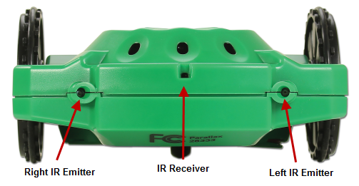
The above image shows the front of your S3. You may notice that your left and right sides are opposite from the labels on the robot. This is because the robot is facing the opposite direction from you – if you turn 180 degrees around, away from the computer screen, you should notice that now your right and left match the robot’s right and left sides. Direction is always determined from the robot’s perspective, not yours. If you keep in mind that the IR emitters and receiver are always facing forward on your robot, you shouldn’t have any problems creating navigation programs with forward, backward, right, and left direction commands.
The emitters send alternating pulses of infrared light which are reflected back to the receiver only after hitting an obstacle. Since only one LED flashes at a time, your S3 can figure out which LED was emitting light when the receiver detected a reflection. It will use this information to decide on which side the obstacle lies. If the object is directly in front, then the light from both LEDs will reflect to the receiver when they flash.
Every robot sensor has advantages and disadvantages, with each having certain physical limitations. How it is positioned on your robot can also have an effect on its performance. Infrared does not effectively see black objects because they absorb the infrared light instead of reflecting it back to the receiver. The infrared object sensing system on the S3 works best when objects are not too dark in color, and are located between 1” and 12” from the front of the robot.

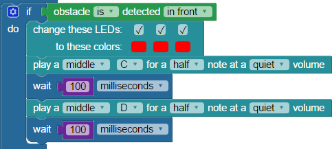
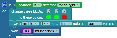
We can create a program in BlocklyProp that demonstrates behavior similar to the Demo 3 program (obstacle detection without roaming).

The loop command makes the program run continuously. If an obstacle is not detected, all LEDs will appear green. If an obstacle is directly in front of the S3, all the LEDs will appear red. Obstacles to the left are indicated by a single red LED on the left side, and an obstacle on the right is indicated by a single red LED on the right side.

It should be fairly easy now to modify either of the programs above into an obstacle avoidance program. Can you see how?
Special thanks to Parallax friend Whit Stodghill for his assistance in writing, editing, and testing material for these S3 tutorials.
The ability to make a robot follow light (or run away from light like a bug on your kitchen floor) was an early goal of robotics’ research. Why light following? There was potential for robots to be able to use light, particularly sunlight, as a renewable source of power. NASA and JPL’s Mars Spirit and Opportunity robotic rovers use solar panels to recharge their batteries. It makes sense then that such robots might be programmed to seek out light, and avoid darkness.
Hyperion, an experimental robot, was developed by roboticists at the Robotics Institute at Pittsburgh’s Carnegie Mellon University, CMU. Sent to the arctic and desert regions of our planet, Hyperion was developed to explore the idea of a moving a solar-powered robot that seeks sunlight to keep its batteries charged. This concept might lead to robotic rovers that could operate semi-autonomously for years, on the Moon or distant planets. The robot’s name, Hyperion, comes from Greek mythology. Hyperion, when translated, means “he who follows the Sun.”
Source: http://www.frc.ri.cmu.edu/atacama/atacama2003-05/hyperion.html
The front of the S3 has three phototransistor light sensors: small, black, oval-shaped holes. They allow your robot measure the ambient (or surrounding) light. A phototransistor light sensor is a sensor that reacts to light in a predictable way. When light hits the tiny chip inside the sensor’s clear plastic case, current is allowed to flow through the the circuit. More light equals more current flow. The S3 continually measures this current and interprets it as levels of ambient light, then uses this information to execute light-seeking or light-avoiding programs.
This image shows the location of the S3’s three phototransistor light sensors; they are located within the shell to protect them from harm.
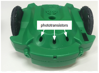
Important Note: Do not insert any object into these sensor holes! These sensors can be easily damaged by sticking a Sharpie® pen tip, or any other object in these openings. Permanent marker ink will blackout the sensor’s clear plastic case, rendering the sensor unusable.
Now, how do we use these sensors to help us see the light?
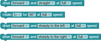
The S3’s first demo monitored the light sensors and used the indicator LEDs to give visual feedback, showing varying light levels with different colors (green, amber, etc). Let’s create a slightly simpler program that does something similar, to familiarize you with how to use the detect light block. The following blocks are are found in the CONTROL, SENSOR, and ACTIONS categories.

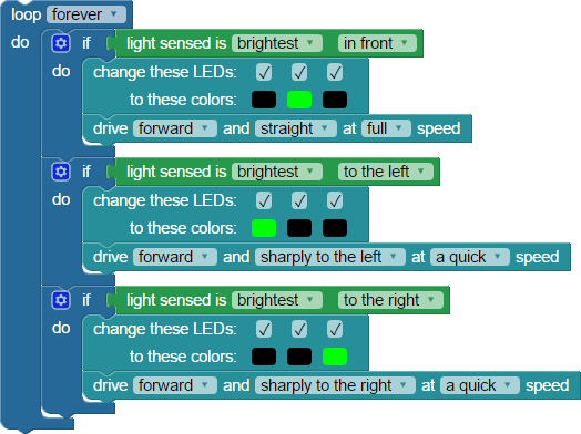
To break things down a little, lets discuss what these blocks are doing. Starting with a loop block makes the program repeat endlessly. Then, the detect light block (repeated three times here) reads each of the S3’s phototransistors to figure out which is seeing the most light. The change LEDs block sets to green whichever indicator LED corresponds to the side with most light, and turns the other LEDs off.
In this example a single LED is lit up green based on where the light sensor finds the most light – front (center), left, or right. If you can do something like light an LED based on a sensor reading, you can just as easily program the S3 to drive at the brightest light source instead.

This program tries to always drive straight at the brightest light source. If that brightest source is not located directly in front, this program will turn your S3 clockwise or counterclockwise until it can aim straight for the light. It’s close, but it’s not quite a fully autonomous navigation program yet, so let’s keep going.
Early robot hobbyists in B.E.A.M. robotics developed a number of terms to describe how robots interact with light:
For more information see Wikipedia’s B.E.A.M. robotics article at: https://en.wikipedia.org/wiki/BEAM_robotics.
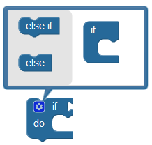
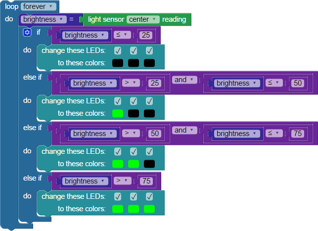
The three previous examples are the most basic way in BlocklyProp to write a light following example for the S3. There are more advanced ways to write a light following program, such as with if…do blocks that use else if conditions.
In an if…do…else if…do statement, if the condition being tested is true, the do statement runs. If the condition being tested is false, the else if statement runs. To create else or else if statements, click the gear icon in the upper left of the block and choose the conditions you want by draging the small else if or else into the if block. Your program may require any number of else or else if blocks, depending on how many conditions you are testing.

Light Brightness Meter
You can use the other light sensor reading block to measure how bright the light being measured by the light sensor is. If you combine that with the boolean comparison and compare values blocks found in the MATH menu, it is possible to build a light guage.
Recreate the program below to turn your Scribbler robot into a light guage:
Special thanks to Parallax friend Whit Stodghill for his assistance in writing, editing, and testing material for these S3 tutorials.
In this tutorial, you will look at the line sensor reading block from the SENSORS > LINE menu. While the detect line block gives us data about whether the sensor is or is not over a line, the light sensor reading block gives us more detailed information:
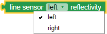
It provides a value of 0% to 100% that tells us how reflective the material under the Scribbler Robot is for either the left or right line sensors.
This program uses blocks from the CONTROL, VARIABLES, SENSOR > LINE, and ACTIONS > COMMUNICATE categories. The Terminal send blocks will send the sensor values to your computer so that you can see what they are returning.
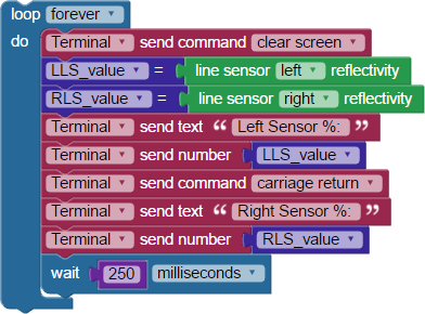
Inside the loop forever block, the values for both the right and left line sensors from the light sensor reading blocks are stored in variables. The values in those variables are then sent to the terminal so that you can see the measurements.
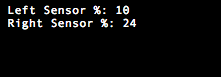
The cable provides a link between the robot and the BlocklyProp Terminal software. When the program begins, the Terminal window will open. When the S3 makes a connection with the Terminal, you should see something like this (your numbers may differ):
Now, you can experiment with the S3’s line sensors to try and understand how they work.
If you want, conduct similar tests with a 3/4” black masking tape line, 3/4” black electrical tape line, or a 3/4” wide Sharpie® marker line – all on white paper or poster board. You can also try white lines on a dark or black surface.
An example chart is below, with extra spaces for additional line types you might want to try:

*Example readings in the “inkjet black/white paper” column are in the example code illustrations. Your results will vary.
Now, you need to find the middle point between dark and light for the left sensor and the middle point between dark and light for the right sensor, separately.
The left sensor got a low reading of 10% and a high reading of 57%. The midpoint (average) is 33% (rounded to a whole number). Left sensor readings below 33% mean it’s above a dark color, and readings at or above 33% indicate it’s above a light color.
The right sensor had a low reading of 11% and a high reading of 65%. The midpoint (average) is 38%. Right sensor readings below 38% indicate a dark color, and readings at or above 38% indicate a light color.
Remember, the midpoints for your S3 robot will probably be different.
Using VARIABLES blocks, MATH blocks, and the line sensor reading block, you can create a line sensing program optimized for your unique Scribbler robot. The variables are as below. Remember that creating a new variable creates both a set variable and a use variable block.
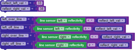
To check the function of the variable blocks you just created, let’s add some LED feedback. Using what you’ve made so far, along with additional blocks from the CONTROL and ACTIONS > LEDs categories, construct the BlocklyProp code below:
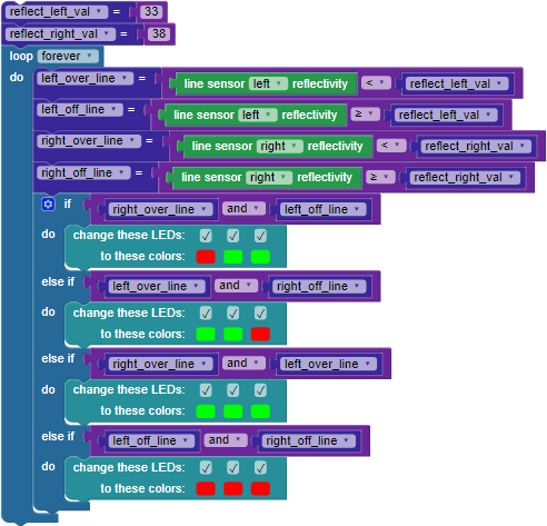
Do you get the correct LED feedback as the robot moves relative to the black line? If not, recheck your work against the examples and try again. If yes, let’s try following a line.
In the following Try This and Your Turn sections, you will be programming the S3 to follow lines using more advanced BlocklyProp blocks. It may require some experimentation with different settings and different blocks to get the program working. To be successful, and to avoid becoming overwhelmed, make sure you test your program after every change keeping track of what works and what doesn’t. When you have things functioning as you want them to, be sure to save the program.
The most common approach to dealing with a large task you are unfamiliar with is with trial and error – by trying different ideas, failing, and then learning from your mistakes. This approach works best when you carefully work through problems and solve them in small, manageable steps. If you have a pen and paper handy, writing your desired program steps down first can also help you determine how to set up your program in the Blockly workspace.
Using the code you created above along with blocks from the ACTIONS > MOTORS category, add the following blocks below the change LEDs blocks to create a line following program in BlocklyProp.


How did it work? How might you improve it? If you are like most experimenters, your S3 may have stopped as soon as it reached any gap in the black line. Remember that the S3 processes info very quickly, so as soon as both sensors simultaneously see a value over your middle threshold, it stops.
Placing the printed sheets edge-to-edge or overlapping them as they are will leave gaps in the line. This is because most printers do not print to the edge of the paper. If you want to create a program that does not stop on these gaps, you are going to have to figure out how to program that in or physically work around them.
Here are some possible solutions:
Hint: You will need to re-check reflectivity and possibly determine a new middle threshold value if you make a line from a different material or ink. You may have already done this at the beginning of this tutorial.
Special thanks to Parallax friend Whit Stodghill for his assistance in writing, editing, and testing material for these S3 tutorials.