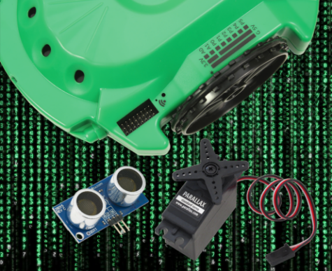
The Scribbler 3 Hacker Port offers unlimited potential for expanding your robot with additional sensors and devices like the PING))) Ultrasonic Distance Sensor, Parallax Standard Servo, and more.
The tutorials in this section will teach you how to use the exposed Hacker Port to connect and integrate peripheral sensors into your BlocklyProp programs.
You will need a window or tab open to the BlocklyProp website to follow along with these tutorials.
Before you begin, you should have already completed:
If you are ready to proceed, click the following links to get started!
One of the standard warnings on many electronic gadgets is that opening the case voids the manufacturer’s warranty. This has discouraged many users from hacking, or making creative modifications to a device. But, it has served as a dare to others to boldly void the warranty and hack away!
Luckily, hacking the S3 is not discouraged but is instead encouraged. To support and encourage hacking, the S3 includes an exposed and labeled Hacker Port. HACK away! As Parallax President Ken Gracey says, “If you can’t hack it, you don’t own it!”
First let’s find the Hacker Port and then look at the pins made available for us to use. Then, let’s try connecting two different circuits to the Hacker Port: an LED, and then a rear bumper.
Other household items needed are listed with each circuit below.
The term hacker first appeared in the 1960s. It was used to describe a programmer or someone who hacked or modified computer code (oftentimes to cause harm to the computer or its users). Today the term is used more broadly, including to describe someone who has an advanced understanding of computers, networking, programming, or hardware, but who hacks as a hobby or as a way to improve code, or hardware. A hacker culture has developed among a larger commjunity, called Makers, who create, modify or re-purpose all sorts of things. In our case – robots!
Roboticists love to hack. We encourage this practice, so we made sure that the S3 Hacker Port is fully exposed and situated right on the top of the robot. Take a look at your S3, or at the labeled diagram of the top part of the shell that is included in your Startup Guide. The Hacker Port is on the left hand side next to the front of the left drive wheel. Inside the port you will see three columns and eight rows of pins. These pins are your direct connection to the powerful inner working of the S3 robot. What is so great about these pins being exposed? You don’t have to open the robot’s case to access them. Adding a peripheral sensor can be as easy as simply plugging in a cable.
Each of these pins has a purpose. To understand the purpose of each pin, engineers create what is called a Pinout diagram. Your Hacker Port label shows pin numbering, supply voltage, and ground connection.
The pinout diagrams for Propeller microcontrollers are very detailed. If you’re curious, do an online search for “Parallax Propeller pinout.” You will notice that the Propeller microcontroller has a lot more pins than what is available on our Hacker Port. Many of these, however, are reserved for monitoring and controlling the many built-in sensors and other features of your S3 robot.
Let’s look at this pinout diagram of the S3’s Hacker Port, taken from the S3 User Guide included with your Scribbler.

Let’s try doing something useful with a few of the pins in the Hacker Port.
A diode is an electrical part that only lets electricity flow through it in one direction. A light-emitting diode (LED) emits light when current passes through it. In order for an LED to light up, it must be connected in the correct way. If you plug an LED in backward it will not emit light.
An LED has two terminals: the anode and the cathode. The anode lead, the wide part of the triangle in the schematic symbol, is labeled with the plus-sign (+). The cathode lead, labeled with a minus-sign (-), is the verticle line across the point of the triangle in the schematic symbol.
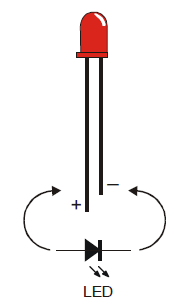
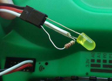
You can tell the anode and cathode apart by the shape of the LED’s plastic case. Look closely – it’s mostly round, but there is a small flat area near the cathode lead. Also note that the LED’s leads are different lengths. Usually, the shorter lead is connected to the cathode.
Always check the LED’s plastic case. Sometimes the leads have been clipped to the same length, or a manufacturer does not follow this convention.
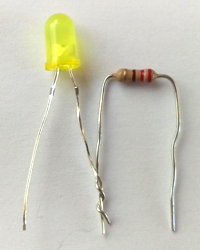
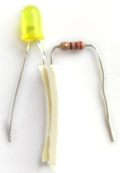
One of the simplest things you can attach to the Hacker Port is an LED. To build an LED circuit for your Scribbler Robot, you will need the items below:
Before connecting anything to your Scribbler robot’s Hacker Port, make sure your Scribbler is turned off and unplugged from its programming cable!
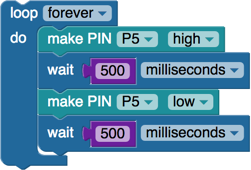
Your LED should now be blinking!
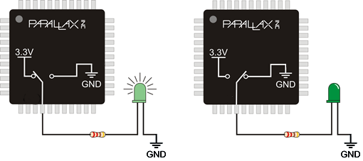
When P5 is turned high by the make pin block, that means it begins sending a positive voltage out of that pin. That positive voltage pushes an electrical current through the resistor and then the LED. Since the LED is connected to Ground, the circuit is completed and the LED glows. When the make pin block sets P5 low, both ends of the circuit are at zero volts, which means there is no voltage to push an electrical current through the LED, which makes it stop glowing.
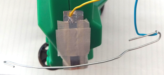
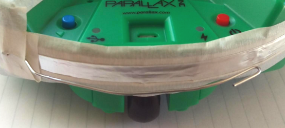
The Scribbler Robot has an infrared obstacle detector in the front, but it has no way to know if it backs into an obstacle. Using a few simple materials, you can add a rear obstacle detector (bumper) to your Scribbler!
You will need:
Make sure your Scribbler robot is turned off before connecting anything to the Hacker Port.
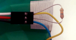
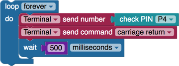

The check pin block sets P4 to an input. This means that it senses when voltage is (or is not) applied to it. The resistor “pulls” the signal pin (white wire) up to a positive voltage so that when the bumper is not pressed, the value of the check pin block will be 1. When the paperclip touches the foil, the signal wire becomes connected directly to ground (0 volts). This means that when the bumper is pressed, the value of the check pin block will be 0.
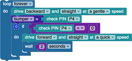
Your Scribbler will drive backward until it bumps into something. Then it will drive forward for 2 seconds before driving backwards again.
Special thanks to Parallax friend Whit Stodghill for his assistance in writing, editing, and testing material for these S3 tutorials.
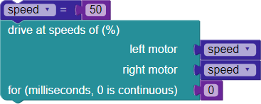
Let’s start putting the S3’s Hacker Port to use by connecting and controlling a Parallax Standard Servo. This tutorial will first demonstrate how to make a Standard Servo hold three different positions, and then how to approximate smooth, continuous motion with small, evenly-timed changes in position. With the S3’s Hacker Port, the physical connection is extremely easy and with BlocklyProp, coding is greatly simplified.
You will need the following accessory parts:
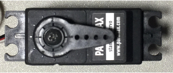
A hobby servo is a small device that controls the position of flaps, rudders, and steering in many radio-controlled toy planes, boats, and cars. The Parallax Standard Servo is a hobby servo that can also be useful in many robotics and animatronics projects. Since it can both move to and hold a position, it is ideal for tasks like rotating a distance sensor or controlling the fingers in a robotic hand.
For more information on Standard Servos and how they work, see: Propeller C Simple Devices – Standard Servo.
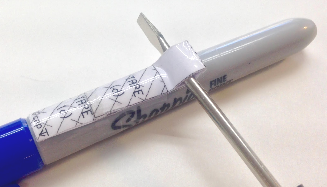
It helps to create some sort of angle marker on the turning part of the servo, the horn, to more easily indicate which position it is in. A jumper wire or twist-tie works well for this.

A Parallax Standard Servo is rated for a 4 to 6 V (volt) supply. The S3 User Guide notes that the S3 provides regulated 5V power, Ground (G) and access to I/O Pins 0 – 5 from the Hacker Port. Connections to 3.3 V power and Analog Pins 0 and 1 are also available from the Hacker Port.
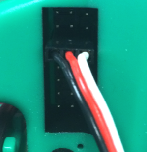
All the info you need to properly connect the servo to your S3 is in the image below. Remember that it is printed right on the surface of your S3 directly adjacent to the Hacker Port. As you can see, there are 8 rows of pins arranged in 3 columns.
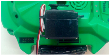
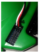
Make sure the power is off on your S3 and it is unplugged from your programming/charging cable. Connect the Standard Servo’s black/red/white cable connector to the pin row marked P0. Orient the connector so that the black wire is connected to the Ground column, the red wire is connected to the middle (5V), and the white signal connector is on the pin column – all along the row marked P0. Be careful not to accidently connect it to one of the rows labeled A0 or A1.
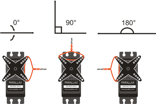
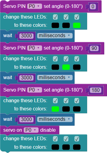
Now, you can write the BlocklyProp Standard Servo test program to hold the three positions shown above. The code should move the servo to the three positions (0°, 90°, and 180° ) with three seconds to move between and hold each position. This code will also change the indicator LEDs based on the servo position. While the program is running, the servo will resist any attempt to move it out of position. When the program finishes, the servo will stop resisting.
In the ACTIONS > MOTORS category, you will find the rotate servo block and disable servo block. Other blocks will not be discussed, as they were used in previous tutorials.
With BlocklyProp, the code explains itself:
As the image above shows, the rotate servo block allows you to set two parameters: the pin the servo is connected to and the servo angle in degrees. For example, to make the servo connected to P0 turn to 90-degrees, the block is set to P0 and 90. Keep in mind that the rotate servo block does not wait for the servo to get into position – it is necessary to include a wait block for the servo to reach the desired position before setting a new angle. Finally, the disable servo block makes sure that pulses to the servo are ended.
Note: Standard Servos have a 180-degree range, plus or minus small differences between individual units. Be careful not to enter a servo angle greater than 180 degrees or you could damage the motor.
Special thanks to Parallax friend Whit Stodghill for his assistance in writing, editing, and testing material for these S3 tutorials.
Suppose you want to use your S3 to scribble the word “Robot”. If you wanted each letter to be separate, you would need to remove the pen tip from the drawing surface between each letter. In handwriting or drawing terms, this is called a pen lift. (Here is a video of a Parallax S2 doing just that.)
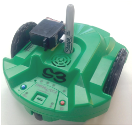
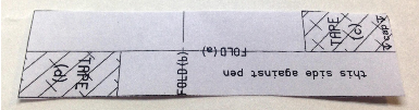
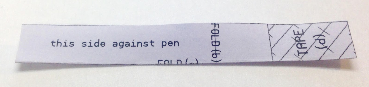
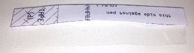
In a previous tutorial, you learned how to control a Standard Servo by connecting it to your S3’s Hacker Port. In the pen lift hack, you can use a servo to lift the pen between letters or for other special purposes when we are scribbling. Follow this tutorial to learn how.
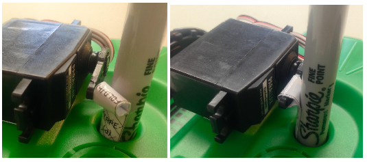
The video below shows the mechanical assembly of the pen lift device.
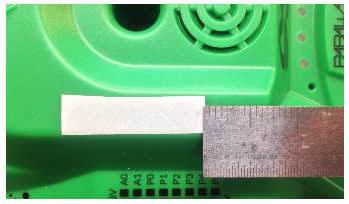
Photos, instructions, and the pdf print-out you will need are listed below. It is a simple and creative way to add a pen lifter to your S3 using a Standard Servo and some simple tools.

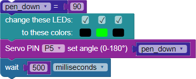
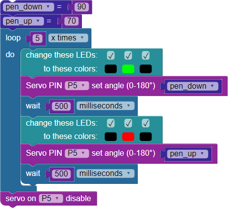
This code depicts the following: First, you add a pen_up set variable block. Your values may vary – see note below. Next, you loop the body of the code 5 times. A green LED indicates that the pen is down, where it stays for 500 ms. The red LED shows that the pen is up, again for 500 ms. As before, the servo is attached to P5. Finally, you disable the servo when finished.
Note: pen_down and pen_up values will vary based on your servo position, paper loop size and position, but the 20 degrees between values should be close to correct. Play with it to find out what works best for you.

Did your S3 do what you expected? If not, check out the Youtube Video of this program in action here.
Special thanks to Parallax friend Whit Stodghill for his assistance in writing, editing, and testing material for these S3 tutorials.
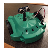
The PING))) measures the round-trip echo time of ultrasonic sound to determine how far away an object is, and can measure distances anywhere from 3 centimeters to 3 meters. In addition to being a great distance sensor for robots, the PING))) is also useful for things such as detecting when a person passes through a doorway, approaches art exhibits, and walks near holiday props.
Want to go a bit more in depth? Check out this article about the speed of sound vs. air temperature, and learn how the temperature of your environment can impact distance measurements from your PING))) sensor.
The PING))) sensor only needs three connections to do its job: I/O pin, power, and ground. The connections are easily accessible at the Hacker Port, making for a simple hacking project with the S3. BlocklyProp makes programming the PING))) simple and fun.
To complete this tutorial, you will need these parts:
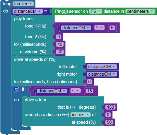
Let’s have some fun in BlocklyProp and test some code. This particular code will display the distance in centimeters to an object placed in front of the sensor, providing Terminal and LED feedback.
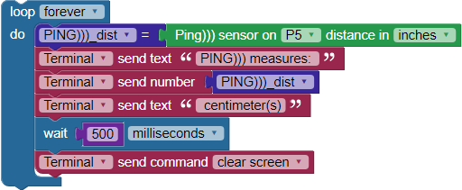
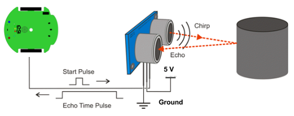
After the PING))) sensor receives a low-high-low start pulse from the S3’s Propeller Chip, it makes a brief ultrasonic chirping sound. Humans cannot hear this ultrasonic cound, but it is loud enough that its own ultrasonic transducer can detect when the echo comes back.
As soon as the PING))) sensor makes its chirp, it sets its output pin high. When the echo comes back, it sets the pin low. The Propeller measures how long the PING))) sensor holds this pin high. This number is the round trip time it takes for the sound to return.
The BlocklyProp Ping))) distance block contains functions that send the start pulse and measure the echo time pulse. It also utilizes functions that use the speed of sound in air to convert the echo time to a specified distance as set in the block.
Special thanks to Parallax friend Whit Stodghill for his assistance in writing, editing, and testing material for these S3 tutorials.