The white board with lots of square sockets in it is called a solderless breadboard. This breadboard has 17 rows of sockets. In each row, there are two five-socket groups separated by a trench in the middle. All the sockets in a 5-socket group are connected together underneath with a conductive metal clip. So, two wires plugged into the same 5‑socket group make electrical contact. This is how you will connect components, such as an LED and resistor, to build circuits. Two wires in the same row on opposite sides of the center trench will not be connected.
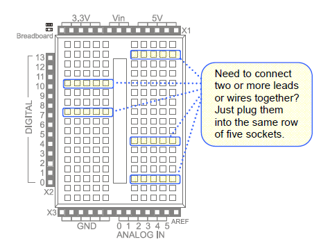
The prototyping area also has black sockets along the top, bottom, and left.
Digital and analog pins are the small pins on the Arduino module’s Atmel microcontroller chip. These pins electrically connect the microcontroller brain to the board.
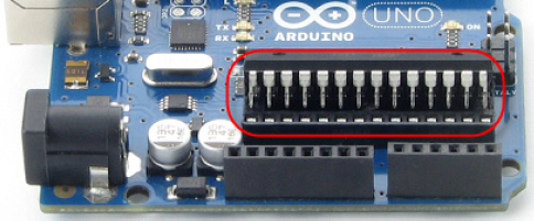
A sketch can make the digital pins send high or low signals to circuits. In this chapter, we’ll do that to turn lights on and off. A sketch can also make a digital pin monitor high or low signals coming from a circuit; We’ll do that in another chapter to detect whether a contact switch has been pressed or released.
A sketch can also measure the voltages applied to analog pins; we’ll do that to measure light with a phototransistor circuit in another chapter.
