A timing diagram is a graph that relates a signal's high and low stages to time. This timing diagram shows you a 1000 ms slice of the HIGH (5 V) and LOW (0 V) signals from the sketch HighLowLed. Can you see how delay(500) is controlling the blink rate?
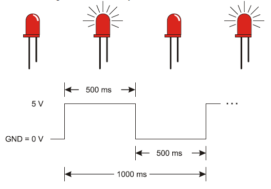
How would you make the LED blink twice as fast? How about reducing the delay function’s ms parameters by half?
Blinking the pin 12 LED is a simple matter of changing the pin parameter in the pinMode and two digitalWrite function calls.
You can also make both LEDs blink at the same time.
  pinMode(13, OUTPUT);         // Set digital pin 13 -> output
  pinMode(12, OUTPUT);         // Set digital pin 12 -> output
  digitalWrite(13, HIGH);      // Pin 13 = 5 V, LED emits light
  digitalWrite(12, HIGH);      // Pin 12 = 5 V, LED emits light
  delay(500);                  // ..for 0.5 seconds
  digitalWrite(13, LOW);       // Pin 13 = 0 V, LED no light
  digitalWrite(12, LOW);       // Pin 12 = 0 V, LED no light
  delay(500);                  // ..for 0.5 seconds
How would you modify the sketch again to turn one LED on while the other turns off? One circuit will need to receive a HIGH signal while the other receives a LOW signal.
