In this activity, you will build and test the infrared object sensor system to make sure they detect objects in front of the ActivityBot. Just like the whisker circuits, there is one on the right and one on the left so the ActivityBot can determine which way to turn in relation to the obstacle.
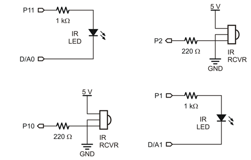
In this case, each side needs two electronic components: an LED that rapidly flashes infrared light, and an infrared receiver to detect a reflection of that infrared light bouncing off of objects nearby.
(2) IR LEDs
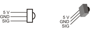
(2) IR receivers
(2) 1 k-ohm resistors (brown-black-red)
(2) 220-ohm resistors (red-red-brown)
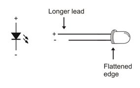
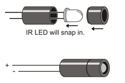
The infrared LEDs are designed to sit in the standoff tubes a certain way. The flat spot on the LED dome matches a flat ledge inside the tube. Holes on the bottom of the tube are labeled for the anode (+) and cathode (-) leads.
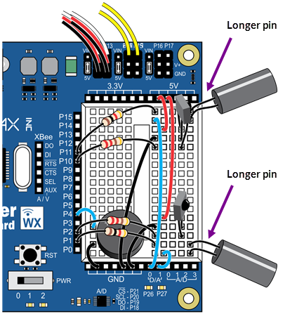
To direct the IR LED’s light, just like a flashlight beam, we’ll use an IR LED standoff (longer tube) and shield (shorter tube). The style of the standoff and light shield may vary, but they still fit together the same way.
The IR LED’s cathodes are connected to the D/A0 and D/A1 sockets on the Activity Board WX. These two special sockets can output a variable voltage. This voltage can be increased to make the IR LEDs dimmer, for closer range detection. (They can even be tested at different voltages—levels of dimness—to get a rough idea of the object’s distance, but that's for another activity...)