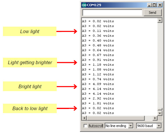
The PhototransistorVoltage sketch makes the Serial Monitor display the voltage measured at A3—one of the Arduino’s five analog input channels that are accessible through the BOE Shield. In the circuit you just built, a wire connects A3 to the row where the phototransistor’s emitter and resistor meet. The voltage at this part of the circuit will change as the light level sensed by the phototransistor changes. The Serial Monitor screencapture below shows some example voltage measurements.
/*
 * Robotics with the BOE Shield - PhototransistorVoltage
 * Display voltage of phototransistor circuit output connected to A3 in
 * the serial monitor.
 */

void setup()                                 // Built-in initialization block
{
  Serial.begin(9600);                        // Set data rate to 9600 bps
}

void loop()                                  // Main loop auto-repeats
{
  Serial.print("A3 = ");                     // Display "A3 = "
  Serial.print(volts(A3));                    // Display measured A3 volts
  Serial.println(" volts");                  // Display " volts" & newline
  delay(1000);                               // Delay for 1 second
}

float volts(int adPin)                       // Measures volts at adPin
{                                            // Returns floating point voltage
 return float(analogRead(adPin)) * 5.0 / 1024.0;
}
