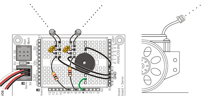
These circuits can respond independently to the light level reaching each phototransistor. They will be pointing upward at about 45°, one forward-left and the other forward-right. This way, a sketch monitoring the values of both phototransistors can determine which side of the BOE Shield-Bot sees brighter light. Then, this information can be used for navigation decisions.
(2) phototransistors
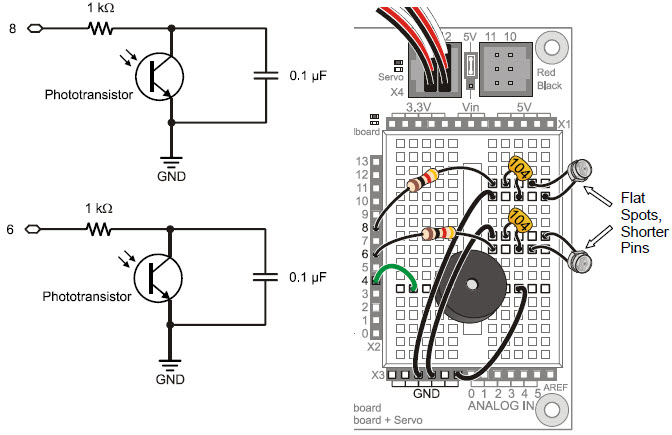
(2) capacitors, 0.1 μF (104)
(2) resistors, 1 kΩ (brown-black-red)
(2) jumper wires
The roaming examples in this chapter will depend on the phototransistors being pointed upward and outward to detect differences in light levels from different directions.
Think of each capacitor in this circuit as a tiny rechargeable battery, and think of each phototransistor as a light-controlled current valve. Each capacitor can be charged to 5 V and then allowed to drain through its phototransistor. The rate that the capacitor loses its charge depends on how much current the phototransistor (current valve) allows to pass, which in turn depends on the brightness of the light shining on the phototransistor’s base. Again, brighter light results in more current passing, shadows result in less current.
This kind of phototransistor/capacitor circuit is called a charge transfer circuit. The Arduino will determine the rate at which each capacitor loses its charge through its phototransistor by measuring how long it takes the capacitor’s voltage to decay, that is, to drop below a certain voltage value. The decay time corresponds to how wide open that current valve is, which is controlled by the brightness of the light reaching the phototransistor’s base. More light means faster decay, less light means slower decay.

QT Circuit: A common abbreviation for charge transfer is QT. The letter Q refers to electrical charge (an accumulation of electrons), and T is for transfer.
Connected in Parallel: The phototransistor and capacitor shown in Figure 6‑11 are connected in parallel; each of their leads are connected to common terminals (also called nodes). The phototransistor and the capacitor each have one lead connected to GND, and they also each have one lead connected to the same 1 kΩ resistor lead.
