Propeller BlocklyProp Block Reference
-
4×4 Keypad Wiring & Example Code
- 4×4 Keypad Wiring & Example Code
- About Naming Things
- Air Quality BME680
- Badge Display
- 4 x 4 Keypad
- ColorPal Wiring & Code Example
- Sound Impact Wiring & Example Code
- GPS Wiring & Example Code
- PIR Wiring & Example Code
- About BlocklyProp Updates
- Badge LEDs
- Badge Lock
- Joystick Wiring & Example Code
- Fingerprint Scanner Wiring & Example Code
- About Multicore
- Temperature & Humidity Sensor Wiring & Example Code
- Memsic 2125 Wiring & Example Code
- GPS
- System
- Badge Buttons
- PING))) Wiring & Example Code
- RFID Wiring & Example Code
- Graph
- Temp & Humidity
- BlocklyProp Bulk Project Download
- About Board Types
- LIS3DH Accelerometer
- ePaper
- IR Remote Wiring & Example Code
- Fingerprint Scanner
- Arrays
- Advanced WX
- Simple WX
- WX WiFi
- RGB LEDs
- LSM9DS1 9-axis IMU
- Robot
- PWM
- Pulse in / out
- Voltage
- RC time
- Servo
- Audio
- Analog / Pulses
- Memory
- ColorPal
- Sound Impact Sensor
- Sony Remote
- RFID
- PIR
- Ping))) Distance
- MMA7455
- Memsic 2-axis
- 2-Axis Joystick
- HMC5883L
- Sensor
- XBee
- Protocols
- Terminal
- OLED
- Serial LCD
- Communicate
- Pin states
- Functions
- Variables
- Values
- Strings
- Numbers
- Operators
- Control
-
About Naming Things
- 4×4 Keypad Wiring & Example Code
- About Naming Things
- Air Quality BME680
- Badge Display
- 4 x 4 Keypad
- ColorPal Wiring & Code Example
- Sound Impact Wiring & Example Code
- GPS Wiring & Example Code
- PIR Wiring & Example Code
- About BlocklyProp Updates
- Badge LEDs
- Badge Lock
- Joystick Wiring & Example Code
- Fingerprint Scanner Wiring & Example Code
- About Multicore
- Temperature & Humidity Sensor Wiring & Example Code
- Memsic 2125 Wiring & Example Code
- GPS
- System
- Badge Buttons
- PING))) Wiring & Example Code
- RFID Wiring & Example Code
- Graph
- Temp & Humidity
- BlocklyProp Bulk Project Download
- About Board Types
- LIS3DH Accelerometer
- ePaper
- IR Remote Wiring & Example Code
- Fingerprint Scanner
- Arrays
- Advanced WX
- Simple WX
- WX WiFi
- RGB LEDs
- LSM9DS1 9-axis IMU
- Robot
- PWM
- Pulse in / out
- Voltage
- RC time
- Servo
- Audio
- Analog / Pulses
- Memory
- ColorPal
- Sound Impact Sensor
- Sony Remote
- RFID
- PIR
- Ping))) Distance
- MMA7455
- Memsic 2-axis
- 2-Axis Joystick
- HMC5883L
- Sensor
- XBee
- Protocols
- Terminal
- OLED
- Serial LCD
- Communicate
- Pin states
- Functions
- Variables
- Values
- Strings
- Numbers
- Operators
- Control
-
Air Quality BME680
- 4×4 Keypad Wiring & Example Code
- About Naming Things
- Air Quality BME680
- Badge Display
- 4 x 4 Keypad
- ColorPal Wiring & Code Example
- Sound Impact Wiring & Example Code
- GPS Wiring & Example Code
- PIR Wiring & Example Code
- About BlocklyProp Updates
- Badge LEDs
- Badge Lock
- Joystick Wiring & Example Code
- Fingerprint Scanner Wiring & Example Code
- About Multicore
- Temperature & Humidity Sensor Wiring & Example Code
- Memsic 2125 Wiring & Example Code
- GPS
- System
- Badge Buttons
- PING))) Wiring & Example Code
- RFID Wiring & Example Code
- Graph
- Temp & Humidity
- BlocklyProp Bulk Project Download
- About Board Types
- LIS3DH Accelerometer
- ePaper
- IR Remote Wiring & Example Code
- Fingerprint Scanner
- Arrays
- Advanced WX
- Simple WX
- WX WiFi
- RGB LEDs
- LSM9DS1 9-axis IMU
- Robot
- PWM
- Pulse in / out
- Voltage
- RC time
- Servo
- Audio
- Analog / Pulses
- Memory
- ColorPal
- Sound Impact Sensor
- Sony Remote
- RFID
- PIR
- Ping))) Distance
- MMA7455
- Memsic 2-axis
- 2-Axis Joystick
- HMC5883L
- Sensor
- XBee
- Protocols
- Terminal
- OLED
- Serial LCD
- Communicate
- Pin states
- Functions
- Variables
- Values
- Strings
- Numbers
- Operators
- Control
-
Badge Display
- 4×4 Keypad Wiring & Example Code
- About Naming Things
- Air Quality BME680
- Badge Display
- 4 x 4 Keypad
- ColorPal Wiring & Code Example
- Sound Impact Wiring & Example Code
- GPS Wiring & Example Code
- PIR Wiring & Example Code
- About BlocklyProp Updates
- Badge LEDs
- Badge Lock
- Joystick Wiring & Example Code
- Fingerprint Scanner Wiring & Example Code
- About Multicore
- Temperature & Humidity Sensor Wiring & Example Code
- Memsic 2125 Wiring & Example Code
- GPS
- System
- Badge Buttons
- PING))) Wiring & Example Code
- RFID Wiring & Example Code
- Graph
- Temp & Humidity
- BlocklyProp Bulk Project Download
- About Board Types
- LIS3DH Accelerometer
- ePaper
- IR Remote Wiring & Example Code
- Fingerprint Scanner
- Arrays
- Advanced WX
- Simple WX
- WX WiFi
- RGB LEDs
- LSM9DS1 9-axis IMU
- Robot
- PWM
- Pulse in / out
- Voltage
- RC time
- Servo
- Audio
- Analog / Pulses
- Memory
- ColorPal
- Sound Impact Sensor
- Sony Remote
- RFID
- PIR
- Ping))) Distance
- MMA7455
- Memsic 2-axis
- 2-Axis Joystick
- HMC5883L
- Sensor
- XBee
- Protocols
- Terminal
- OLED
- Serial LCD
- Communicate
- Pin states
- Functions
- Variables
- Values
- Strings
- Numbers
- Operators
- Control
-
4 x 4 Keypad
- 4×4 Keypad Wiring & Example Code
- About Naming Things
- Air Quality BME680
- Badge Display
- 4 x 4 Keypad
- ColorPal Wiring & Code Example
- Sound Impact Wiring & Example Code
- GPS Wiring & Example Code
- PIR Wiring & Example Code
- About BlocklyProp Updates
- Badge LEDs
- Badge Lock
- Joystick Wiring & Example Code
- Fingerprint Scanner Wiring & Example Code
- About Multicore
- Temperature & Humidity Sensor Wiring & Example Code
- Memsic 2125 Wiring & Example Code
- GPS
- System
- Badge Buttons
- PING))) Wiring & Example Code
- RFID Wiring & Example Code
- Graph
- Temp & Humidity
- BlocklyProp Bulk Project Download
- About Board Types
- LIS3DH Accelerometer
- ePaper
- IR Remote Wiring & Example Code
- Fingerprint Scanner
- Arrays
- Advanced WX
- Simple WX
- WX WiFi
- RGB LEDs
- LSM9DS1 9-axis IMU
- Robot
- PWM
- Pulse in / out
- Voltage
- RC time
- Servo
- Audio
- Analog / Pulses
- Memory
- ColorPal
- Sound Impact Sensor
- Sony Remote
- RFID
- PIR
- Ping))) Distance
- MMA7455
- Memsic 2-axis
- 2-Axis Joystick
- HMC5883L
- Sensor
- XBee
- Protocols
- Terminal
- OLED
- Serial LCD
- Communicate
- Pin states
- Functions
- Variables
- Values
- Strings
- Numbers
- Operators
- Control
-
ColorPal Wiring & Code Example
- 4×4 Keypad Wiring & Example Code
- About Naming Things
- Air Quality BME680
- Badge Display
- 4 x 4 Keypad
- ColorPal Wiring & Code Example
- Sound Impact Wiring & Example Code
- GPS Wiring & Example Code
- PIR Wiring & Example Code
- About BlocklyProp Updates
- Badge LEDs
- Badge Lock
- Joystick Wiring & Example Code
- Fingerprint Scanner Wiring & Example Code
- About Multicore
- Temperature & Humidity Sensor Wiring & Example Code
- Memsic 2125 Wiring & Example Code
- GPS
- System
- Badge Buttons
- PING))) Wiring & Example Code
- RFID Wiring & Example Code
- Graph
- Temp & Humidity
- BlocklyProp Bulk Project Download
- About Board Types
- LIS3DH Accelerometer
- ePaper
- IR Remote Wiring & Example Code
- Fingerprint Scanner
- Arrays
- Advanced WX
- Simple WX
- WX WiFi
- RGB LEDs
- LSM9DS1 9-axis IMU
- Robot
- PWM
- Pulse in / out
- Voltage
- RC time
- Servo
- Audio
- Analog / Pulses
- Memory
- ColorPal
- Sound Impact Sensor
- Sony Remote
- RFID
- PIR
- Ping))) Distance
- MMA7455
- Memsic 2-axis
- 2-Axis Joystick
- HMC5883L
- Sensor
- XBee
- Protocols
- Terminal
- OLED
- Serial LCD
- Communicate
- Pin states
- Functions
- Variables
- Values
- Strings
- Numbers
- Operators
- Control
-
Sound Impact Wiring & Example Code
- 4×4 Keypad Wiring & Example Code
- About Naming Things
- Air Quality BME680
- Badge Display
- 4 x 4 Keypad
- ColorPal Wiring & Code Example
- Sound Impact Wiring & Example Code
- GPS Wiring & Example Code
- PIR Wiring & Example Code
- About BlocklyProp Updates
- Badge LEDs
- Badge Lock
- Joystick Wiring & Example Code
- Fingerprint Scanner Wiring & Example Code
- About Multicore
- Temperature & Humidity Sensor Wiring & Example Code
- Memsic 2125 Wiring & Example Code
- GPS
- System
- Badge Buttons
- PING))) Wiring & Example Code
- RFID Wiring & Example Code
- Graph
- Temp & Humidity
- BlocklyProp Bulk Project Download
- About Board Types
- LIS3DH Accelerometer
- ePaper
- IR Remote Wiring & Example Code
- Fingerprint Scanner
- Arrays
- Advanced WX
- Simple WX
- WX WiFi
- RGB LEDs
- LSM9DS1 9-axis IMU
- Robot
- PWM
- Pulse in / out
- Voltage
- RC time
- Servo
- Audio
- Analog / Pulses
- Memory
- ColorPal
- Sound Impact Sensor
- Sony Remote
- RFID
- PIR
- Ping))) Distance
- MMA7455
- Memsic 2-axis
- 2-Axis Joystick
- HMC5883L
- Sensor
- XBee
- Protocols
- Terminal
- OLED
- Serial LCD
- Communicate
- Pin states
- Functions
- Variables
- Values
- Strings
- Numbers
- Operators
- Control
-
GPS Wiring & Example Code
- 4×4 Keypad Wiring & Example Code
- About Naming Things
- Air Quality BME680
- Badge Display
- 4 x 4 Keypad
- ColorPal Wiring & Code Example
- Sound Impact Wiring & Example Code
- GPS Wiring & Example Code
- PIR Wiring & Example Code
- About BlocklyProp Updates
- Badge LEDs
- Badge Lock
- Joystick Wiring & Example Code
- Fingerprint Scanner Wiring & Example Code
- About Multicore
- Temperature & Humidity Sensor Wiring & Example Code
- Memsic 2125 Wiring & Example Code
- GPS
- System
- Badge Buttons
- PING))) Wiring & Example Code
- RFID Wiring & Example Code
- Graph
- Temp & Humidity
- BlocklyProp Bulk Project Download
- About Board Types
- LIS3DH Accelerometer
- ePaper
- IR Remote Wiring & Example Code
- Fingerprint Scanner
- Arrays
- Advanced WX
- Simple WX
- WX WiFi
- RGB LEDs
- LSM9DS1 9-axis IMU
- Robot
- PWM
- Pulse in / out
- Voltage
- RC time
- Servo
- Audio
- Analog / Pulses
- Memory
- ColorPal
- Sound Impact Sensor
- Sony Remote
- RFID
- PIR
- Ping))) Distance
- MMA7455
- Memsic 2-axis
- 2-Axis Joystick
- HMC5883L
- Sensor
- XBee
- Protocols
- Terminal
- OLED
- Serial LCD
- Communicate
- Pin states
- Functions
- Variables
- Values
- Strings
- Numbers
- Operators
- Control
-
PIR Wiring & Example Code
- 4×4 Keypad Wiring & Example Code
- About Naming Things
- Air Quality BME680
- Badge Display
- 4 x 4 Keypad
- ColorPal Wiring & Code Example
- Sound Impact Wiring & Example Code
- GPS Wiring & Example Code
- PIR Wiring & Example Code
- About BlocklyProp Updates
- Badge LEDs
- Badge Lock
- Joystick Wiring & Example Code
- Fingerprint Scanner Wiring & Example Code
- About Multicore
- Temperature & Humidity Sensor Wiring & Example Code
- Memsic 2125 Wiring & Example Code
- GPS
- System
- Badge Buttons
- PING))) Wiring & Example Code
- RFID Wiring & Example Code
- Graph
- Temp & Humidity
- BlocklyProp Bulk Project Download
- About Board Types
- LIS3DH Accelerometer
- ePaper
- IR Remote Wiring & Example Code
- Fingerprint Scanner
- Arrays
- Advanced WX
- Simple WX
- WX WiFi
- RGB LEDs
- LSM9DS1 9-axis IMU
- Robot
- PWM
- Pulse in / out
- Voltage
- RC time
- Servo
- Audio
- Analog / Pulses
- Memory
- ColorPal
- Sound Impact Sensor
- Sony Remote
- RFID
- PIR
- Ping))) Distance
- MMA7455
- Memsic 2-axis
- 2-Axis Joystick
- HMC5883L
- Sensor
- XBee
- Protocols
- Terminal
- OLED
- Serial LCD
- Communicate
- Pin states
- Functions
- Variables
- Values
- Strings
- Numbers
- Operators
- Control
-
About BlocklyProp Updates
- 4×4 Keypad Wiring & Example Code
- About Naming Things
- Air Quality BME680
- Badge Display
- 4 x 4 Keypad
- ColorPal Wiring & Code Example
- Sound Impact Wiring & Example Code
- GPS Wiring & Example Code
- PIR Wiring & Example Code
- About BlocklyProp Updates
- Badge LEDs
- Badge Lock
- Joystick Wiring & Example Code
- Fingerprint Scanner Wiring & Example Code
- About Multicore
- Temperature & Humidity Sensor Wiring & Example Code
- Memsic 2125 Wiring & Example Code
- GPS
- System
- Badge Buttons
- PING))) Wiring & Example Code
- RFID Wiring & Example Code
- Graph
- Temp & Humidity
- BlocklyProp Bulk Project Download
- About Board Types
- LIS3DH Accelerometer
- ePaper
- IR Remote Wiring & Example Code
- Fingerprint Scanner
- Arrays
- Advanced WX
- Simple WX
- WX WiFi
- RGB LEDs
- LSM9DS1 9-axis IMU
- Robot
- PWM
- Pulse in / out
- Voltage
- RC time
- Servo
- Audio
- Analog / Pulses
- Memory
- ColorPal
- Sound Impact Sensor
- Sony Remote
- RFID
- PIR
- Ping))) Distance
- MMA7455
- Memsic 2-axis
- 2-Axis Joystick
- HMC5883L
- Sensor
- XBee
- Protocols
- Terminal
- OLED
- Serial LCD
- Communicate
- Pin states
- Functions
- Variables
- Values
- Strings
- Numbers
- Operators
- Control
-
Badge LEDs
- 4×4 Keypad Wiring & Example Code
- About Naming Things
- Air Quality BME680
- Badge Display
- 4 x 4 Keypad
- ColorPal Wiring & Code Example
- Sound Impact Wiring & Example Code
- GPS Wiring & Example Code
- PIR Wiring & Example Code
- About BlocklyProp Updates
- Badge LEDs
- Badge Lock
- Joystick Wiring & Example Code
- Fingerprint Scanner Wiring & Example Code
- About Multicore
- Temperature & Humidity Sensor Wiring & Example Code
- Memsic 2125 Wiring & Example Code
- GPS
- System
- Badge Buttons
- PING))) Wiring & Example Code
- RFID Wiring & Example Code
- Graph
- Temp & Humidity
- BlocklyProp Bulk Project Download
- About Board Types
- LIS3DH Accelerometer
- ePaper
- IR Remote Wiring & Example Code
- Fingerprint Scanner
- Arrays
- Advanced WX
- Simple WX
- WX WiFi
- RGB LEDs
- LSM9DS1 9-axis IMU
- Robot
- PWM
- Pulse in / out
- Voltage
- RC time
- Servo
- Audio
- Analog / Pulses
- Memory
- ColorPal
- Sound Impact Sensor
- Sony Remote
- RFID
- PIR
- Ping))) Distance
- MMA7455
- Memsic 2-axis
- 2-Axis Joystick
- HMC5883L
- Sensor
- XBee
- Protocols
- Terminal
- OLED
- Serial LCD
- Communicate
- Pin states
- Functions
- Variables
- Values
- Strings
- Numbers
- Operators
- Control
-
Badge Lock
- 4×4 Keypad Wiring & Example Code
- About Naming Things
- Air Quality BME680
- Badge Display
- 4 x 4 Keypad
- ColorPal Wiring & Code Example
- Sound Impact Wiring & Example Code
- GPS Wiring & Example Code
- PIR Wiring & Example Code
- About BlocklyProp Updates
- Badge LEDs
- Badge Lock
- Joystick Wiring & Example Code
- Fingerprint Scanner Wiring & Example Code
- About Multicore
- Temperature & Humidity Sensor Wiring & Example Code
- Memsic 2125 Wiring & Example Code
- GPS
- System
- Badge Buttons
- PING))) Wiring & Example Code
- RFID Wiring & Example Code
- Graph
- Temp & Humidity
- BlocklyProp Bulk Project Download
- About Board Types
- LIS3DH Accelerometer
- ePaper
- IR Remote Wiring & Example Code
- Fingerprint Scanner
- Arrays
- Advanced WX
- Simple WX
- WX WiFi
- RGB LEDs
- LSM9DS1 9-axis IMU
- Robot
- PWM
- Pulse in / out
- Voltage
- RC time
- Servo
- Audio
- Analog / Pulses
- Memory
- ColorPal
- Sound Impact Sensor
- Sony Remote
- RFID
- PIR
- Ping))) Distance
- MMA7455
- Memsic 2-axis
- 2-Axis Joystick
- HMC5883L
- Sensor
- XBee
- Protocols
- Terminal
- OLED
- Serial LCD
- Communicate
- Pin states
- Functions
- Variables
- Values
- Strings
- Numbers
- Operators
- Control
-
Joystick Wiring & Example Code
- 4×4 Keypad Wiring & Example Code
- About Naming Things
- Air Quality BME680
- Badge Display
- 4 x 4 Keypad
- ColorPal Wiring & Code Example
- Sound Impact Wiring & Example Code
- GPS Wiring & Example Code
- PIR Wiring & Example Code
- About BlocklyProp Updates
- Badge LEDs
- Badge Lock
- Joystick Wiring & Example Code
- Fingerprint Scanner Wiring & Example Code
- About Multicore
- Temperature & Humidity Sensor Wiring & Example Code
- Memsic 2125 Wiring & Example Code
- GPS
- System
- Badge Buttons
- PING))) Wiring & Example Code
- RFID Wiring & Example Code
- Graph
- Temp & Humidity
- BlocklyProp Bulk Project Download
- About Board Types
- LIS3DH Accelerometer
- ePaper
- IR Remote Wiring & Example Code
- Fingerprint Scanner
- Arrays
- Advanced WX
- Simple WX
- WX WiFi
- RGB LEDs
- LSM9DS1 9-axis IMU
- Robot
- PWM
- Pulse in / out
- Voltage
- RC time
- Servo
- Audio
- Analog / Pulses
- Memory
- ColorPal
- Sound Impact Sensor
- Sony Remote
- RFID
- PIR
- Ping))) Distance
- MMA7455
- Memsic 2-axis
- 2-Axis Joystick
- HMC5883L
- Sensor
- XBee
- Protocols
- Terminal
- OLED
- Serial LCD
- Communicate
- Pin states
- Functions
- Variables
- Values
- Strings
- Numbers
- Operators
- Control
-
Fingerprint Scanner Wiring & Example Code
- 4×4 Keypad Wiring & Example Code
- About Naming Things
- Air Quality BME680
- Badge Display
- 4 x 4 Keypad
- ColorPal Wiring & Code Example
- Sound Impact Wiring & Example Code
- GPS Wiring & Example Code
- PIR Wiring & Example Code
- About BlocklyProp Updates
- Badge LEDs
- Badge Lock
- Joystick Wiring & Example Code
- Fingerprint Scanner Wiring & Example Code
- About Multicore
- Temperature & Humidity Sensor Wiring & Example Code
- Memsic 2125 Wiring & Example Code
- GPS
- System
- Badge Buttons
- PING))) Wiring & Example Code
- RFID Wiring & Example Code
- Graph
- Temp & Humidity
- BlocklyProp Bulk Project Download
- About Board Types
- LIS3DH Accelerometer
- ePaper
- IR Remote Wiring & Example Code
- Fingerprint Scanner
- Arrays
- Advanced WX
- Simple WX
- WX WiFi
- RGB LEDs
- LSM9DS1 9-axis IMU
- Robot
- PWM
- Pulse in / out
- Voltage
- RC time
- Servo
- Audio
- Analog / Pulses
- Memory
- ColorPal
- Sound Impact Sensor
- Sony Remote
- RFID
- PIR
- Ping))) Distance
- MMA7455
- Memsic 2-axis
- 2-Axis Joystick
- HMC5883L
- Sensor
- XBee
- Protocols
- Terminal
- OLED
- Serial LCD
- Communicate
- Pin states
- Functions
- Variables
- Values
- Strings
- Numbers
- Operators
- Control
-
About Multicore
- 4×4 Keypad Wiring & Example Code
- About Naming Things
- Air Quality BME680
- Badge Display
- 4 x 4 Keypad
- ColorPal Wiring & Code Example
- Sound Impact Wiring & Example Code
- GPS Wiring & Example Code
- PIR Wiring & Example Code
- About BlocklyProp Updates
- Badge LEDs
- Badge Lock
- Joystick Wiring & Example Code
- Fingerprint Scanner Wiring & Example Code
- About Multicore
- Temperature & Humidity Sensor Wiring & Example Code
- Memsic 2125 Wiring & Example Code
- GPS
- System
- Badge Buttons
- PING))) Wiring & Example Code
- RFID Wiring & Example Code
- Graph
- Temp & Humidity
- BlocklyProp Bulk Project Download
- About Board Types
- LIS3DH Accelerometer
- ePaper
- IR Remote Wiring & Example Code
- Fingerprint Scanner
- Arrays
- Advanced WX
- Simple WX
- WX WiFi
- RGB LEDs
- LSM9DS1 9-axis IMU
- Robot
- PWM
- Pulse in / out
- Voltage
- RC time
- Servo
- Audio
- Analog / Pulses
- Memory
- ColorPal
- Sound Impact Sensor
- Sony Remote
- RFID
- PIR
- Ping))) Distance
- MMA7455
- Memsic 2-axis
- 2-Axis Joystick
- HMC5883L
- Sensor
- XBee
- Protocols
- Terminal
- OLED
- Serial LCD
- Communicate
- Pin states
- Functions
- Variables
- Values
- Strings
- Numbers
- Operators
- Control
-
Temperature & Humidity Sensor Wiring & Example Code
- 4×4 Keypad Wiring & Example Code
- About Naming Things
- Air Quality BME680
- Badge Display
- 4 x 4 Keypad
- ColorPal Wiring & Code Example
- Sound Impact Wiring & Example Code
- GPS Wiring & Example Code
- PIR Wiring & Example Code
- About BlocklyProp Updates
- Badge LEDs
- Badge Lock
- Joystick Wiring & Example Code
- Fingerprint Scanner Wiring & Example Code
- About Multicore
- Temperature & Humidity Sensor Wiring & Example Code
- Memsic 2125 Wiring & Example Code
- GPS
- System
- Badge Buttons
- PING))) Wiring & Example Code
- RFID Wiring & Example Code
- Graph
- Temp & Humidity
- BlocklyProp Bulk Project Download
- About Board Types
- LIS3DH Accelerometer
- ePaper
- IR Remote Wiring & Example Code
- Fingerprint Scanner
- Arrays
- Advanced WX
- Simple WX
- WX WiFi
- RGB LEDs
- LSM9DS1 9-axis IMU
- Robot
- PWM
- Pulse in / out
- Voltage
- RC time
- Servo
- Audio
- Analog / Pulses
- Memory
- ColorPal
- Sound Impact Sensor
- Sony Remote
- RFID
- PIR
- Ping))) Distance
- MMA7455
- Memsic 2-axis
- 2-Axis Joystick
- HMC5883L
- Sensor
- XBee
- Protocols
- Terminal
- OLED
- Serial LCD
- Communicate
- Pin states
- Functions
- Variables
- Values
- Strings
- Numbers
- Operators
- Control
-
Memsic 2125 Wiring & Example Code
- 4×4 Keypad Wiring & Example Code
- About Naming Things
- Air Quality BME680
- Badge Display
- 4 x 4 Keypad
- ColorPal Wiring & Code Example
- Sound Impact Wiring & Example Code
- GPS Wiring & Example Code
- PIR Wiring & Example Code
- About BlocklyProp Updates
- Badge LEDs
- Badge Lock
- Joystick Wiring & Example Code
- Fingerprint Scanner Wiring & Example Code
- About Multicore
- Temperature & Humidity Sensor Wiring & Example Code
- Memsic 2125 Wiring & Example Code
- GPS
- System
- Badge Buttons
- PING))) Wiring & Example Code
- RFID Wiring & Example Code
- Graph
- Temp & Humidity
- BlocklyProp Bulk Project Download
- About Board Types
- LIS3DH Accelerometer
- ePaper
- IR Remote Wiring & Example Code
- Fingerprint Scanner
- Arrays
- Advanced WX
- Simple WX
- WX WiFi
- RGB LEDs
- LSM9DS1 9-axis IMU
- Robot
- PWM
- Pulse in / out
- Voltage
- RC time
- Servo
- Audio
- Analog / Pulses
- Memory
- ColorPal
- Sound Impact Sensor
- Sony Remote
- RFID
- PIR
- Ping))) Distance
- MMA7455
- Memsic 2-axis
- 2-Axis Joystick
- HMC5883L
- Sensor
- XBee
- Protocols
- Terminal
- OLED
- Serial LCD
- Communicate
- Pin states
- Functions
- Variables
- Values
- Strings
- Numbers
- Operators
- Control
-
GPS
- 4×4 Keypad Wiring & Example Code
- About Naming Things
- Air Quality BME680
- Badge Display
- 4 x 4 Keypad
- ColorPal Wiring & Code Example
- Sound Impact Wiring & Example Code
- GPS Wiring & Example Code
- PIR Wiring & Example Code
- About BlocklyProp Updates
- Badge LEDs
- Badge Lock
- Joystick Wiring & Example Code
- Fingerprint Scanner Wiring & Example Code
- About Multicore
- Temperature & Humidity Sensor Wiring & Example Code
- Memsic 2125 Wiring & Example Code
- GPS
- System
- Badge Buttons
- PING))) Wiring & Example Code
- RFID Wiring & Example Code
- Graph
- Temp & Humidity
- BlocklyProp Bulk Project Download
- About Board Types
- LIS3DH Accelerometer
- ePaper
- IR Remote Wiring & Example Code
- Fingerprint Scanner
- Arrays
- Advanced WX
- Simple WX
- WX WiFi
- RGB LEDs
- LSM9DS1 9-axis IMU
- Robot
- PWM
- Pulse in / out
- Voltage
- RC time
- Servo
- Audio
- Analog / Pulses
- Memory
- ColorPal
- Sound Impact Sensor
- Sony Remote
- RFID
- PIR
- Ping))) Distance
- MMA7455
- Memsic 2-axis
- 2-Axis Joystick
- HMC5883L
- Sensor
- XBee
- Protocols
- Terminal
- OLED
- Serial LCD
- Communicate
- Pin states
- Functions
- Variables
- Values
- Strings
- Numbers
- Operators
- Control
-
System
- 4×4 Keypad Wiring & Example Code
- About Naming Things
- Air Quality BME680
- Badge Display
- 4 x 4 Keypad
- ColorPal Wiring & Code Example
- Sound Impact Wiring & Example Code
- GPS Wiring & Example Code
- PIR Wiring & Example Code
- About BlocklyProp Updates
- Badge LEDs
- Badge Lock
- Joystick Wiring & Example Code
- Fingerprint Scanner Wiring & Example Code
- About Multicore
- Temperature & Humidity Sensor Wiring & Example Code
- Memsic 2125 Wiring & Example Code
- GPS
- System
- Badge Buttons
- PING))) Wiring & Example Code
- RFID Wiring & Example Code
- Graph
- Temp & Humidity
- BlocklyProp Bulk Project Download
- About Board Types
- LIS3DH Accelerometer
- ePaper
- IR Remote Wiring & Example Code
- Fingerprint Scanner
- Arrays
- Advanced WX
- Simple WX
- WX WiFi
- RGB LEDs
- LSM9DS1 9-axis IMU
- Robot
- PWM
- Pulse in / out
- Voltage
- RC time
- Servo
- Audio
- Analog / Pulses
- Memory
- ColorPal
- Sound Impact Sensor
- Sony Remote
- RFID
- PIR
- Ping))) Distance
- MMA7455
- Memsic 2-axis
- 2-Axis Joystick
- HMC5883L
- Sensor
- XBee
- Protocols
- Terminal
- OLED
- Serial LCD
- Communicate
- Pin states
- Functions
- Variables
- Values
- Strings
- Numbers
- Operators
- Control
-
Badge Buttons
- 4×4 Keypad Wiring & Example Code
- About Naming Things
- Air Quality BME680
- Badge Display
- 4 x 4 Keypad
- ColorPal Wiring & Code Example
- Sound Impact Wiring & Example Code
- GPS Wiring & Example Code
- PIR Wiring & Example Code
- About BlocklyProp Updates
- Badge LEDs
- Badge Lock
- Joystick Wiring & Example Code
- Fingerprint Scanner Wiring & Example Code
- About Multicore
- Temperature & Humidity Sensor Wiring & Example Code
- Memsic 2125 Wiring & Example Code
- GPS
- System
- Badge Buttons
- PING))) Wiring & Example Code
- RFID Wiring & Example Code
- Graph
- Temp & Humidity
- BlocklyProp Bulk Project Download
- About Board Types
- LIS3DH Accelerometer
- ePaper
- IR Remote Wiring & Example Code
- Fingerprint Scanner
- Arrays
- Advanced WX
- Simple WX
- WX WiFi
- RGB LEDs
- LSM9DS1 9-axis IMU
- Robot
- PWM
- Pulse in / out
- Voltage
- RC time
- Servo
- Audio
- Analog / Pulses
- Memory
- ColorPal
- Sound Impact Sensor
- Sony Remote
- RFID
- PIR
- Ping))) Distance
- MMA7455
- Memsic 2-axis
- 2-Axis Joystick
- HMC5883L
- Sensor
- XBee
- Protocols
- Terminal
- OLED
- Serial LCD
- Communicate
- Pin states
- Functions
- Variables
- Values
- Strings
- Numbers
- Operators
- Control
-
PING))) Wiring & Example Code
- 4×4 Keypad Wiring & Example Code
- About Naming Things
- Air Quality BME680
- Badge Display
- 4 x 4 Keypad
- ColorPal Wiring & Code Example
- Sound Impact Wiring & Example Code
- GPS Wiring & Example Code
- PIR Wiring & Example Code
- About BlocklyProp Updates
- Badge LEDs
- Badge Lock
- Joystick Wiring & Example Code
- Fingerprint Scanner Wiring & Example Code
- About Multicore
- Temperature & Humidity Sensor Wiring & Example Code
- Memsic 2125 Wiring & Example Code
- GPS
- System
- Badge Buttons
- PING))) Wiring & Example Code
- RFID Wiring & Example Code
- Graph
- Temp & Humidity
- BlocklyProp Bulk Project Download
- About Board Types
- LIS3DH Accelerometer
- ePaper
- IR Remote Wiring & Example Code
- Fingerprint Scanner
- Arrays
- Advanced WX
- Simple WX
- WX WiFi
- RGB LEDs
- LSM9DS1 9-axis IMU
- Robot
- PWM
- Pulse in / out
- Voltage
- RC time
- Servo
- Audio
- Analog / Pulses
- Memory
- ColorPal
- Sound Impact Sensor
- Sony Remote
- RFID
- PIR
- Ping))) Distance
- MMA7455
- Memsic 2-axis
- 2-Axis Joystick
- HMC5883L
- Sensor
- XBee
- Protocols
- Terminal
- OLED
- Serial LCD
- Communicate
- Pin states
- Functions
- Variables
- Values
- Strings
- Numbers
- Operators
- Control
-
RFID Wiring & Example Code
- 4×4 Keypad Wiring & Example Code
- About Naming Things
- Air Quality BME680
- Badge Display
- 4 x 4 Keypad
- ColorPal Wiring & Code Example
- Sound Impact Wiring & Example Code
- GPS Wiring & Example Code
- PIR Wiring & Example Code
- About BlocklyProp Updates
- Badge LEDs
- Badge Lock
- Joystick Wiring & Example Code
- Fingerprint Scanner Wiring & Example Code
- About Multicore
- Temperature & Humidity Sensor Wiring & Example Code
- Memsic 2125 Wiring & Example Code
- GPS
- System
- Badge Buttons
- PING))) Wiring & Example Code
- RFID Wiring & Example Code
- Graph
- Temp & Humidity
- BlocklyProp Bulk Project Download
- About Board Types
- LIS3DH Accelerometer
- ePaper
- IR Remote Wiring & Example Code
- Fingerprint Scanner
- Arrays
- Advanced WX
- Simple WX
- WX WiFi
- RGB LEDs
- LSM9DS1 9-axis IMU
- Robot
- PWM
- Pulse in / out
- Voltage
- RC time
- Servo
- Audio
- Analog / Pulses
- Memory
- ColorPal
- Sound Impact Sensor
- Sony Remote
- RFID
- PIR
- Ping))) Distance
- MMA7455
- Memsic 2-axis
- 2-Axis Joystick
- HMC5883L
- Sensor
- XBee
- Protocols
- Terminal
- OLED
- Serial LCD
- Communicate
- Pin states
- Functions
- Variables
- Values
- Strings
- Numbers
- Operators
- Control
-
Graph
- 4×4 Keypad Wiring & Example Code
- About Naming Things
- Air Quality BME680
- Badge Display
- 4 x 4 Keypad
- ColorPal Wiring & Code Example
- Sound Impact Wiring & Example Code
- GPS Wiring & Example Code
- PIR Wiring & Example Code
- About BlocklyProp Updates
- Badge LEDs
- Badge Lock
- Joystick Wiring & Example Code
- Fingerprint Scanner Wiring & Example Code
- About Multicore
- Temperature & Humidity Sensor Wiring & Example Code
- Memsic 2125 Wiring & Example Code
- GPS
- System
- Badge Buttons
- PING))) Wiring & Example Code
- RFID Wiring & Example Code
- Graph
- Temp & Humidity
- BlocklyProp Bulk Project Download
- About Board Types
- LIS3DH Accelerometer
- ePaper
- IR Remote Wiring & Example Code
- Fingerprint Scanner
- Arrays
- Advanced WX
- Simple WX
- WX WiFi
- RGB LEDs
- LSM9DS1 9-axis IMU
- Robot
- PWM
- Pulse in / out
- Voltage
- RC time
- Servo
- Audio
- Analog / Pulses
- Memory
- ColorPal
- Sound Impact Sensor
- Sony Remote
- RFID
- PIR
- Ping))) Distance
- MMA7455
- Memsic 2-axis
- 2-Axis Joystick
- HMC5883L
- Sensor
- XBee
- Protocols
- Terminal
- OLED
- Serial LCD
- Communicate
- Pin states
- Functions
- Variables
- Values
- Strings
- Numbers
- Operators
- Control
-
Temp & Humidity
- 4×4 Keypad Wiring & Example Code
- About Naming Things
- Air Quality BME680
- Badge Display
- 4 x 4 Keypad
- ColorPal Wiring & Code Example
- Sound Impact Wiring & Example Code
- GPS Wiring & Example Code
- PIR Wiring & Example Code
- About BlocklyProp Updates
- Badge LEDs
- Badge Lock
- Joystick Wiring & Example Code
- Fingerprint Scanner Wiring & Example Code
- About Multicore
- Temperature & Humidity Sensor Wiring & Example Code
- Memsic 2125 Wiring & Example Code
- GPS
- System
- Badge Buttons
- PING))) Wiring & Example Code
- RFID Wiring & Example Code
- Graph
- Temp & Humidity
- BlocklyProp Bulk Project Download
- About Board Types
- LIS3DH Accelerometer
- ePaper
- IR Remote Wiring & Example Code
- Fingerprint Scanner
- Arrays
- Advanced WX
- Simple WX
- WX WiFi
- RGB LEDs
- LSM9DS1 9-axis IMU
- Robot
- PWM
- Pulse in / out
- Voltage
- RC time
- Servo
- Audio
- Analog / Pulses
- Memory
- ColorPal
- Sound Impact Sensor
- Sony Remote
- RFID
- PIR
- Ping))) Distance
- MMA7455
- Memsic 2-axis
- 2-Axis Joystick
- HMC5883L
- Sensor
- XBee
- Protocols
- Terminal
- OLED
- Serial LCD
- Communicate
- Pin states
- Functions
- Variables
- Values
- Strings
- Numbers
- Operators
- Control
-
BlocklyProp Bulk Project Download
- 4×4 Keypad Wiring & Example Code
- About Naming Things
- Air Quality BME680
- Badge Display
- 4 x 4 Keypad
- ColorPal Wiring & Code Example
- Sound Impact Wiring & Example Code
- GPS Wiring & Example Code
- PIR Wiring & Example Code
- About BlocklyProp Updates
- Badge LEDs
- Badge Lock
- Joystick Wiring & Example Code
- Fingerprint Scanner Wiring & Example Code
- About Multicore
- Temperature & Humidity Sensor Wiring & Example Code
- Memsic 2125 Wiring & Example Code
- GPS
- System
- Badge Buttons
- PING))) Wiring & Example Code
- RFID Wiring & Example Code
- Graph
- Temp & Humidity
- BlocklyProp Bulk Project Download
- About Board Types
- LIS3DH Accelerometer
- ePaper
- IR Remote Wiring & Example Code
- Fingerprint Scanner
- Arrays
- Advanced WX
- Simple WX
- WX WiFi
- RGB LEDs
- LSM9DS1 9-axis IMU
- Robot
- PWM
- Pulse in / out
- Voltage
- RC time
- Servo
- Audio
- Analog / Pulses
- Memory
- ColorPal
- Sound Impact Sensor
- Sony Remote
- RFID
- PIR
- Ping))) Distance
- MMA7455
- Memsic 2-axis
- 2-Axis Joystick
- HMC5883L
- Sensor
- XBee
- Protocols
- Terminal
- OLED
- Serial LCD
- Communicate
- Pin states
- Functions
- Variables
- Values
- Strings
- Numbers
- Operators
- Control
-
About Board Types
- 4×4 Keypad Wiring & Example Code
- About Naming Things
- Air Quality BME680
- Badge Display
- 4 x 4 Keypad
- ColorPal Wiring & Code Example
- Sound Impact Wiring & Example Code
- GPS Wiring & Example Code
- PIR Wiring & Example Code
- About BlocklyProp Updates
- Badge LEDs
- Badge Lock
- Joystick Wiring & Example Code
- Fingerprint Scanner Wiring & Example Code
- About Multicore
- Temperature & Humidity Sensor Wiring & Example Code
- Memsic 2125 Wiring & Example Code
- GPS
- System
- Badge Buttons
- PING))) Wiring & Example Code
- RFID Wiring & Example Code
- Graph
- Temp & Humidity
- BlocklyProp Bulk Project Download
- About Board Types
- LIS3DH Accelerometer
- ePaper
- IR Remote Wiring & Example Code
- Fingerprint Scanner
- Arrays
- Advanced WX
- Simple WX
- WX WiFi
- RGB LEDs
- LSM9DS1 9-axis IMU
- Robot
- PWM
- Pulse in / out
- Voltage
- RC time
- Servo
- Audio
- Analog / Pulses
- Memory
- ColorPal
- Sound Impact Sensor
- Sony Remote
- RFID
- PIR
- Ping))) Distance
- MMA7455
- Memsic 2-axis
- 2-Axis Joystick
- HMC5883L
- Sensor
- XBee
- Protocols
- Terminal
- OLED
- Serial LCD
- Communicate
- Pin states
- Functions
- Variables
- Values
- Strings
- Numbers
- Operators
- Control
-
LIS3DH Accelerometer
- 4×4 Keypad Wiring & Example Code
- About Naming Things
- Air Quality BME680
- Badge Display
- 4 x 4 Keypad
- ColorPal Wiring & Code Example
- Sound Impact Wiring & Example Code
- GPS Wiring & Example Code
- PIR Wiring & Example Code
- About BlocklyProp Updates
- Badge LEDs
- Badge Lock
- Joystick Wiring & Example Code
- Fingerprint Scanner Wiring & Example Code
- About Multicore
- Temperature & Humidity Sensor Wiring & Example Code
- Memsic 2125 Wiring & Example Code
- GPS
- System
- Badge Buttons
- PING))) Wiring & Example Code
- RFID Wiring & Example Code
- Graph
- Temp & Humidity
- BlocklyProp Bulk Project Download
- About Board Types
- LIS3DH Accelerometer
- ePaper
- IR Remote Wiring & Example Code
- Fingerprint Scanner
- Arrays
- Advanced WX
- Simple WX
- WX WiFi
- RGB LEDs
- LSM9DS1 9-axis IMU
- Robot
- PWM
- Pulse in / out
- Voltage
- RC time
- Servo
- Audio
- Analog / Pulses
- Memory
- ColorPal
- Sound Impact Sensor
- Sony Remote
- RFID
- PIR
- Ping))) Distance
- MMA7455
- Memsic 2-axis
- 2-Axis Joystick
- HMC5883L
- Sensor
- XBee
- Protocols
- Terminal
- OLED
- Serial LCD
- Communicate
- Pin states
- Functions
- Variables
- Values
- Strings
- Numbers
- Operators
- Control
-
ePaper
- 4×4 Keypad Wiring & Example Code
- About Naming Things
- Air Quality BME680
- Badge Display
- 4 x 4 Keypad
- ColorPal Wiring & Code Example
- Sound Impact Wiring & Example Code
- GPS Wiring & Example Code
- PIR Wiring & Example Code
- About BlocklyProp Updates
- Badge LEDs
- Badge Lock
- Joystick Wiring & Example Code
- Fingerprint Scanner Wiring & Example Code
- About Multicore
- Temperature & Humidity Sensor Wiring & Example Code
- Memsic 2125 Wiring & Example Code
- GPS
- System
- Badge Buttons
- PING))) Wiring & Example Code
- RFID Wiring & Example Code
- Graph
- Temp & Humidity
- BlocklyProp Bulk Project Download
- About Board Types
- LIS3DH Accelerometer
- ePaper
- IR Remote Wiring & Example Code
- Fingerprint Scanner
- Arrays
- Advanced WX
- Simple WX
- WX WiFi
- RGB LEDs
- LSM9DS1 9-axis IMU
- Robot
- PWM
- Pulse in / out
- Voltage
- RC time
- Servo
- Audio
- Analog / Pulses
- Memory
- ColorPal
- Sound Impact Sensor
- Sony Remote
- RFID
- PIR
- Ping))) Distance
- MMA7455
- Memsic 2-axis
- 2-Axis Joystick
- HMC5883L
- Sensor
- XBee
- Protocols
- Terminal
- OLED
- Serial LCD
- Communicate
- Pin states
- Functions
- Variables
- Values
- Strings
- Numbers
- Operators
- Control
-
IR Remote Wiring & Example Code
- 4×4 Keypad Wiring & Example Code
- About Naming Things
- Air Quality BME680
- Badge Display
- 4 x 4 Keypad
- ColorPal Wiring & Code Example
- Sound Impact Wiring & Example Code
- GPS Wiring & Example Code
- PIR Wiring & Example Code
- About BlocklyProp Updates
- Badge LEDs
- Badge Lock
- Joystick Wiring & Example Code
- Fingerprint Scanner Wiring & Example Code
- About Multicore
- Temperature & Humidity Sensor Wiring & Example Code
- Memsic 2125 Wiring & Example Code
- GPS
- System
- Badge Buttons
- PING))) Wiring & Example Code
- RFID Wiring & Example Code
- Graph
- Temp & Humidity
- BlocklyProp Bulk Project Download
- About Board Types
- LIS3DH Accelerometer
- ePaper
- IR Remote Wiring & Example Code
- Fingerprint Scanner
- Arrays
- Advanced WX
- Simple WX
- WX WiFi
- RGB LEDs
- LSM9DS1 9-axis IMU
- Robot
- PWM
- Pulse in / out
- Voltage
- RC time
- Servo
- Audio
- Analog / Pulses
- Memory
- ColorPal
- Sound Impact Sensor
- Sony Remote
- RFID
- PIR
- Ping))) Distance
- MMA7455
- Memsic 2-axis
- 2-Axis Joystick
- HMC5883L
- Sensor
- XBee
- Protocols
- Terminal
- OLED
- Serial LCD
- Communicate
- Pin states
- Functions
- Variables
- Values
- Strings
- Numbers
- Operators
- Control
-
Fingerprint Scanner
- 4×4 Keypad Wiring & Example Code
- About Naming Things
- Air Quality BME680
- Badge Display
- 4 x 4 Keypad
- ColorPal Wiring & Code Example
- Sound Impact Wiring & Example Code
- GPS Wiring & Example Code
- PIR Wiring & Example Code
- About BlocklyProp Updates
- Badge LEDs
- Badge Lock
- Joystick Wiring & Example Code
- Fingerprint Scanner Wiring & Example Code
- About Multicore
- Temperature & Humidity Sensor Wiring & Example Code
- Memsic 2125 Wiring & Example Code
- GPS
- System
- Badge Buttons
- PING))) Wiring & Example Code
- RFID Wiring & Example Code
- Graph
- Temp & Humidity
- BlocklyProp Bulk Project Download
- About Board Types
- LIS3DH Accelerometer
- ePaper
- IR Remote Wiring & Example Code
- Fingerprint Scanner
- Arrays
- Advanced WX
- Simple WX
- WX WiFi
- RGB LEDs
- LSM9DS1 9-axis IMU
- Robot
- PWM
- Pulse in / out
- Voltage
- RC time
- Servo
- Audio
- Analog / Pulses
- Memory
- ColorPal
- Sound Impact Sensor
- Sony Remote
- RFID
- PIR
- Ping))) Distance
- MMA7455
- Memsic 2-axis
- 2-Axis Joystick
- HMC5883L
- Sensor
- XBee
- Protocols
- Terminal
- OLED
- Serial LCD
- Communicate
- Pin states
- Functions
- Variables
- Values
- Strings
- Numbers
- Operators
- Control
-
Arrays
- 4×4 Keypad Wiring & Example Code
- About Naming Things
- Air Quality BME680
- Badge Display
- 4 x 4 Keypad
- ColorPal Wiring & Code Example
- Sound Impact Wiring & Example Code
- GPS Wiring & Example Code
- PIR Wiring & Example Code
- About BlocklyProp Updates
- Badge LEDs
- Badge Lock
- Joystick Wiring & Example Code
- Fingerprint Scanner Wiring & Example Code
- About Multicore
- Temperature & Humidity Sensor Wiring & Example Code
- Memsic 2125 Wiring & Example Code
- GPS
- System
- Badge Buttons
- PING))) Wiring & Example Code
- RFID Wiring & Example Code
- Graph
- Temp & Humidity
- BlocklyProp Bulk Project Download
- About Board Types
- LIS3DH Accelerometer
- ePaper
- IR Remote Wiring & Example Code
- Fingerprint Scanner
- Arrays
- Advanced WX
- Simple WX
- WX WiFi
- RGB LEDs
- LSM9DS1 9-axis IMU
- Robot
- PWM
- Pulse in / out
- Voltage
- RC time
- Servo
- Audio
- Analog / Pulses
- Memory
- ColorPal
- Sound Impact Sensor
- Sony Remote
- RFID
- PIR
- Ping))) Distance
- MMA7455
- Memsic 2-axis
- 2-Axis Joystick
- HMC5883L
- Sensor
- XBee
- Protocols
- Terminal
- OLED
- Serial LCD
- Communicate
- Pin states
- Functions
- Variables
- Values
- Strings
- Numbers
- Operators
- Control
-
Advanced WX
- 4×4 Keypad Wiring & Example Code
- About Naming Things
- Air Quality BME680
- Badge Display
- 4 x 4 Keypad
- ColorPal Wiring & Code Example
- Sound Impact Wiring & Example Code
- GPS Wiring & Example Code
- PIR Wiring & Example Code
- About BlocklyProp Updates
- Badge LEDs
- Badge Lock
- Joystick Wiring & Example Code
- Fingerprint Scanner Wiring & Example Code
- About Multicore
- Temperature & Humidity Sensor Wiring & Example Code
- Memsic 2125 Wiring & Example Code
- GPS
- System
- Badge Buttons
- PING))) Wiring & Example Code
- RFID Wiring & Example Code
- Graph
- Temp & Humidity
- BlocklyProp Bulk Project Download
- About Board Types
- LIS3DH Accelerometer
- ePaper
- IR Remote Wiring & Example Code
- Fingerprint Scanner
- Arrays
- Advanced WX
- Simple WX
- WX WiFi
- RGB LEDs
- LSM9DS1 9-axis IMU
- Robot
- PWM
- Pulse in / out
- Voltage
- RC time
- Servo
- Audio
- Analog / Pulses
- Memory
- ColorPal
- Sound Impact Sensor
- Sony Remote
- RFID
- PIR
- Ping))) Distance
- MMA7455
- Memsic 2-axis
- 2-Axis Joystick
- HMC5883L
- Sensor
- XBee
- Protocols
- Terminal
- OLED
- Serial LCD
- Communicate
- Pin states
- Functions
- Variables
- Values
- Strings
- Numbers
- Operators
- Control
-
Simple WX
- 4×4 Keypad Wiring & Example Code
- About Naming Things
- Air Quality BME680
- Badge Display
- 4 x 4 Keypad
- ColorPal Wiring & Code Example
- Sound Impact Wiring & Example Code
- GPS Wiring & Example Code
- PIR Wiring & Example Code
- About BlocklyProp Updates
- Badge LEDs
- Badge Lock
- Joystick Wiring & Example Code
- Fingerprint Scanner Wiring & Example Code
- About Multicore
- Temperature & Humidity Sensor Wiring & Example Code
- Memsic 2125 Wiring & Example Code
- GPS
- System
- Badge Buttons
- PING))) Wiring & Example Code
- RFID Wiring & Example Code
- Graph
- Temp & Humidity
- BlocklyProp Bulk Project Download
- About Board Types
- LIS3DH Accelerometer
- ePaper
- IR Remote Wiring & Example Code
- Fingerprint Scanner
- Arrays
- Advanced WX
- Simple WX
- WX WiFi
- RGB LEDs
- LSM9DS1 9-axis IMU
- Robot
- PWM
- Pulse in / out
- Voltage
- RC time
- Servo
- Audio
- Analog / Pulses
- Memory
- ColorPal
- Sound Impact Sensor
- Sony Remote
- RFID
- PIR
- Ping))) Distance
- MMA7455
- Memsic 2-axis
- 2-Axis Joystick
- HMC5883L
- Sensor
- XBee
- Protocols
- Terminal
- OLED
- Serial LCD
- Communicate
- Pin states
- Functions
- Variables
- Values
- Strings
- Numbers
- Operators
- Control
-
WX WiFi
- 4×4 Keypad Wiring & Example Code
- About Naming Things
- Air Quality BME680
- Badge Display
- 4 x 4 Keypad
- ColorPal Wiring & Code Example
- Sound Impact Wiring & Example Code
- GPS Wiring & Example Code
- PIR Wiring & Example Code
- About BlocklyProp Updates
- Badge LEDs
- Badge Lock
- Joystick Wiring & Example Code
- Fingerprint Scanner Wiring & Example Code
- About Multicore
- Temperature & Humidity Sensor Wiring & Example Code
- Memsic 2125 Wiring & Example Code
- GPS
- System
- Badge Buttons
- PING))) Wiring & Example Code
- RFID Wiring & Example Code
- Graph
- Temp & Humidity
- BlocklyProp Bulk Project Download
- About Board Types
- LIS3DH Accelerometer
- ePaper
- IR Remote Wiring & Example Code
- Fingerprint Scanner
- Arrays
- Advanced WX
- Simple WX
- WX WiFi
- RGB LEDs
- LSM9DS1 9-axis IMU
- Robot
- PWM
- Pulse in / out
- Voltage
- RC time
- Servo
- Audio
- Analog / Pulses
- Memory
- ColorPal
- Sound Impact Sensor
- Sony Remote
- RFID
- PIR
- Ping))) Distance
- MMA7455
- Memsic 2-axis
- 2-Axis Joystick
- HMC5883L
- Sensor
- XBee
- Protocols
- Terminal
- OLED
- Serial LCD
- Communicate
- Pin states
- Functions
- Variables
- Values
- Strings
- Numbers
- Operators
- Control
-
RGB LEDs
- 4×4 Keypad Wiring & Example Code
- About Naming Things
- Air Quality BME680
- Badge Display
- 4 x 4 Keypad
- ColorPal Wiring & Code Example
- Sound Impact Wiring & Example Code
- GPS Wiring & Example Code
- PIR Wiring & Example Code
- About BlocklyProp Updates
- Badge LEDs
- Badge Lock
- Joystick Wiring & Example Code
- Fingerprint Scanner Wiring & Example Code
- About Multicore
- Temperature & Humidity Sensor Wiring & Example Code
- Memsic 2125 Wiring & Example Code
- GPS
- System
- Badge Buttons
- PING))) Wiring & Example Code
- RFID Wiring & Example Code
- Graph
- Temp & Humidity
- BlocklyProp Bulk Project Download
- About Board Types
- LIS3DH Accelerometer
- ePaper
- IR Remote Wiring & Example Code
- Fingerprint Scanner
- Arrays
- Advanced WX
- Simple WX
- WX WiFi
- RGB LEDs
- LSM9DS1 9-axis IMU
- Robot
- PWM
- Pulse in / out
- Voltage
- RC time
- Servo
- Audio
- Analog / Pulses
- Memory
- ColorPal
- Sound Impact Sensor
- Sony Remote
- RFID
- PIR
- Ping))) Distance
- MMA7455
- Memsic 2-axis
- 2-Axis Joystick
- HMC5883L
- Sensor
- XBee
- Protocols
- Terminal
- OLED
- Serial LCD
- Communicate
- Pin states
- Functions
- Variables
- Values
- Strings
- Numbers
- Operators
- Control
-
LSM9DS1 9-axis IMU
- 4×4 Keypad Wiring & Example Code
- About Naming Things
- Air Quality BME680
- Badge Display
- 4 x 4 Keypad
- ColorPal Wiring & Code Example
- Sound Impact Wiring & Example Code
- GPS Wiring & Example Code
- PIR Wiring & Example Code
- About BlocklyProp Updates
- Badge LEDs
- Badge Lock
- Joystick Wiring & Example Code
- Fingerprint Scanner Wiring & Example Code
- About Multicore
- Temperature & Humidity Sensor Wiring & Example Code
- Memsic 2125 Wiring & Example Code
- GPS
- System
- Badge Buttons
- PING))) Wiring & Example Code
- RFID Wiring & Example Code
- Graph
- Temp & Humidity
- BlocklyProp Bulk Project Download
- About Board Types
- LIS3DH Accelerometer
- ePaper
- IR Remote Wiring & Example Code
- Fingerprint Scanner
- Arrays
- Advanced WX
- Simple WX
- WX WiFi
- RGB LEDs
- LSM9DS1 9-axis IMU
- Robot
- PWM
- Pulse in / out
- Voltage
- RC time
- Servo
- Audio
- Analog / Pulses
- Memory
- ColorPal
- Sound Impact Sensor
- Sony Remote
- RFID
- PIR
- Ping))) Distance
- MMA7455
- Memsic 2-axis
- 2-Axis Joystick
- HMC5883L
- Sensor
- XBee
- Protocols
- Terminal
- OLED
- Serial LCD
- Communicate
- Pin states
- Functions
- Variables
- Values
- Strings
- Numbers
- Operators
- Control
-
Robot
- 4×4 Keypad Wiring & Example Code
- About Naming Things
- Air Quality BME680
- Badge Display
- 4 x 4 Keypad
- ColorPal Wiring & Code Example
- Sound Impact Wiring & Example Code
- GPS Wiring & Example Code
- PIR Wiring & Example Code
- About BlocklyProp Updates
- Badge LEDs
- Badge Lock
- Joystick Wiring & Example Code
- Fingerprint Scanner Wiring & Example Code
- About Multicore
- Temperature & Humidity Sensor Wiring & Example Code
- Memsic 2125 Wiring & Example Code
- GPS
- System
- Badge Buttons
- PING))) Wiring & Example Code
- RFID Wiring & Example Code
- Graph
- Temp & Humidity
- BlocklyProp Bulk Project Download
- About Board Types
- LIS3DH Accelerometer
- ePaper
- IR Remote Wiring & Example Code
- Fingerprint Scanner
- Arrays
- Advanced WX
- Simple WX
- WX WiFi
- RGB LEDs
- LSM9DS1 9-axis IMU
- Robot
- PWM
- Pulse in / out
- Voltage
- RC time
- Servo
- Audio
- Analog / Pulses
- Memory
- ColorPal
- Sound Impact Sensor
- Sony Remote
- RFID
- PIR
- Ping))) Distance
- MMA7455
- Memsic 2-axis
- 2-Axis Joystick
- HMC5883L
- Sensor
- XBee
- Protocols
- Terminal
- OLED
- Serial LCD
- Communicate
- Pin states
- Functions
- Variables
- Values
- Strings
- Numbers
- Operators
- Control
-
PWM
- 4×4 Keypad Wiring & Example Code
- About Naming Things
- Air Quality BME680
- Badge Display
- 4 x 4 Keypad
- ColorPal Wiring & Code Example
- Sound Impact Wiring & Example Code
- GPS Wiring & Example Code
- PIR Wiring & Example Code
- About BlocklyProp Updates
- Badge LEDs
- Badge Lock
- Joystick Wiring & Example Code
- Fingerprint Scanner Wiring & Example Code
- About Multicore
- Temperature & Humidity Sensor Wiring & Example Code
- Memsic 2125 Wiring & Example Code
- GPS
- System
- Badge Buttons
- PING))) Wiring & Example Code
- RFID Wiring & Example Code
- Graph
- Temp & Humidity
- BlocklyProp Bulk Project Download
- About Board Types
- LIS3DH Accelerometer
- ePaper
- IR Remote Wiring & Example Code
- Fingerprint Scanner
- Arrays
- Advanced WX
- Simple WX
- WX WiFi
- RGB LEDs
- LSM9DS1 9-axis IMU
- Robot
- PWM
- Pulse in / out
- Voltage
- RC time
- Servo
- Audio
- Analog / Pulses
- Memory
- ColorPal
- Sound Impact Sensor
- Sony Remote
- RFID
- PIR
- Ping))) Distance
- MMA7455
- Memsic 2-axis
- 2-Axis Joystick
- HMC5883L
- Sensor
- XBee
- Protocols
- Terminal
- OLED
- Serial LCD
- Communicate
- Pin states
- Functions
- Variables
- Values
- Strings
- Numbers
- Operators
- Control
-
Pulse in / out
- 4×4 Keypad Wiring & Example Code
- About Naming Things
- Air Quality BME680
- Badge Display
- 4 x 4 Keypad
- ColorPal Wiring & Code Example
- Sound Impact Wiring & Example Code
- GPS Wiring & Example Code
- PIR Wiring & Example Code
- About BlocklyProp Updates
- Badge LEDs
- Badge Lock
- Joystick Wiring & Example Code
- Fingerprint Scanner Wiring & Example Code
- About Multicore
- Temperature & Humidity Sensor Wiring & Example Code
- Memsic 2125 Wiring & Example Code
- GPS
- System
- Badge Buttons
- PING))) Wiring & Example Code
- RFID Wiring & Example Code
- Graph
- Temp & Humidity
- BlocklyProp Bulk Project Download
- About Board Types
- LIS3DH Accelerometer
- ePaper
- IR Remote Wiring & Example Code
- Fingerprint Scanner
- Arrays
- Advanced WX
- Simple WX
- WX WiFi
- RGB LEDs
- LSM9DS1 9-axis IMU
- Robot
- PWM
- Pulse in / out
- Voltage
- RC time
- Servo
- Audio
- Analog / Pulses
- Memory
- ColorPal
- Sound Impact Sensor
- Sony Remote
- RFID
- PIR
- Ping))) Distance
- MMA7455
- Memsic 2-axis
- 2-Axis Joystick
- HMC5883L
- Sensor
- XBee
- Protocols
- Terminal
- OLED
- Serial LCD
- Communicate
- Pin states
- Functions
- Variables
- Values
- Strings
- Numbers
- Operators
- Control
-
Voltage
- 4×4 Keypad Wiring & Example Code
- About Naming Things
- Air Quality BME680
- Badge Display
- 4 x 4 Keypad
- ColorPal Wiring & Code Example
- Sound Impact Wiring & Example Code
- GPS Wiring & Example Code
- PIR Wiring & Example Code
- About BlocklyProp Updates
- Badge LEDs
- Badge Lock
- Joystick Wiring & Example Code
- Fingerprint Scanner Wiring & Example Code
- About Multicore
- Temperature & Humidity Sensor Wiring & Example Code
- Memsic 2125 Wiring & Example Code
- GPS
- System
- Badge Buttons
- PING))) Wiring & Example Code
- RFID Wiring & Example Code
- Graph
- Temp & Humidity
- BlocklyProp Bulk Project Download
- About Board Types
- LIS3DH Accelerometer
- ePaper
- IR Remote Wiring & Example Code
- Fingerprint Scanner
- Arrays
- Advanced WX
- Simple WX
- WX WiFi
- RGB LEDs
- LSM9DS1 9-axis IMU
- Robot
- PWM
- Pulse in / out
- Voltage
- RC time
- Servo
- Audio
- Analog / Pulses
- Memory
- ColorPal
- Sound Impact Sensor
- Sony Remote
- RFID
- PIR
- Ping))) Distance
- MMA7455
- Memsic 2-axis
- 2-Axis Joystick
- HMC5883L
- Sensor
- XBee
- Protocols
- Terminal
- OLED
- Serial LCD
- Communicate
- Pin states
- Functions
- Variables
- Values
- Strings
- Numbers
- Operators
- Control
-
RC time
- 4×4 Keypad Wiring & Example Code
- About Naming Things
- Air Quality BME680
- Badge Display
- 4 x 4 Keypad
- ColorPal Wiring & Code Example
- Sound Impact Wiring & Example Code
- GPS Wiring & Example Code
- PIR Wiring & Example Code
- About BlocklyProp Updates
- Badge LEDs
- Badge Lock
- Joystick Wiring & Example Code
- Fingerprint Scanner Wiring & Example Code
- About Multicore
- Temperature & Humidity Sensor Wiring & Example Code
- Memsic 2125 Wiring & Example Code
- GPS
- System
- Badge Buttons
- PING))) Wiring & Example Code
- RFID Wiring & Example Code
- Graph
- Temp & Humidity
- BlocklyProp Bulk Project Download
- About Board Types
- LIS3DH Accelerometer
- ePaper
- IR Remote Wiring & Example Code
- Fingerprint Scanner
- Arrays
- Advanced WX
- Simple WX
- WX WiFi
- RGB LEDs
- LSM9DS1 9-axis IMU
- Robot
- PWM
- Pulse in / out
- Voltage
- RC time
- Servo
- Audio
- Analog / Pulses
- Memory
- ColorPal
- Sound Impact Sensor
- Sony Remote
- RFID
- PIR
- Ping))) Distance
- MMA7455
- Memsic 2-axis
- 2-Axis Joystick
- HMC5883L
- Sensor
- XBee
- Protocols
- Terminal
- OLED
- Serial LCD
- Communicate
- Pin states
- Functions
- Variables
- Values
- Strings
- Numbers
- Operators
- Control
-
Servo
- 4×4 Keypad Wiring & Example Code
- About Naming Things
- Air Quality BME680
- Badge Display
- 4 x 4 Keypad
- ColorPal Wiring & Code Example
- Sound Impact Wiring & Example Code
- GPS Wiring & Example Code
- PIR Wiring & Example Code
- About BlocklyProp Updates
- Badge LEDs
- Badge Lock
- Joystick Wiring & Example Code
- Fingerprint Scanner Wiring & Example Code
- About Multicore
- Temperature & Humidity Sensor Wiring & Example Code
- Memsic 2125 Wiring & Example Code
- GPS
- System
- Badge Buttons
- PING))) Wiring & Example Code
- RFID Wiring & Example Code
- Graph
- Temp & Humidity
- BlocklyProp Bulk Project Download
- About Board Types
- LIS3DH Accelerometer
- ePaper
- IR Remote Wiring & Example Code
- Fingerprint Scanner
- Arrays
- Advanced WX
- Simple WX
- WX WiFi
- RGB LEDs
- LSM9DS1 9-axis IMU
- Robot
- PWM
- Pulse in / out
- Voltage
- RC time
- Servo
- Audio
- Analog / Pulses
- Memory
- ColorPal
- Sound Impact Sensor
- Sony Remote
- RFID
- PIR
- Ping))) Distance
- MMA7455
- Memsic 2-axis
- 2-Axis Joystick
- HMC5883L
- Sensor
- XBee
- Protocols
- Terminal
- OLED
- Serial LCD
- Communicate
- Pin states
- Functions
- Variables
- Values
- Strings
- Numbers
- Operators
- Control
-
Audio
- 4×4 Keypad Wiring & Example Code
- About Naming Things
- Air Quality BME680
- Badge Display
- 4 x 4 Keypad
- ColorPal Wiring & Code Example
- Sound Impact Wiring & Example Code
- GPS Wiring & Example Code
- PIR Wiring & Example Code
- About BlocklyProp Updates
- Badge LEDs
- Badge Lock
- Joystick Wiring & Example Code
- Fingerprint Scanner Wiring & Example Code
- About Multicore
- Temperature & Humidity Sensor Wiring & Example Code
- Memsic 2125 Wiring & Example Code
- GPS
- System
- Badge Buttons
- PING))) Wiring & Example Code
- RFID Wiring & Example Code
- Graph
- Temp & Humidity
- BlocklyProp Bulk Project Download
- About Board Types
- LIS3DH Accelerometer
- ePaper
- IR Remote Wiring & Example Code
- Fingerprint Scanner
- Arrays
- Advanced WX
- Simple WX
- WX WiFi
- RGB LEDs
- LSM9DS1 9-axis IMU
- Robot
- PWM
- Pulse in / out
- Voltage
- RC time
- Servo
- Audio
- Analog / Pulses
- Memory
- ColorPal
- Sound Impact Sensor
- Sony Remote
- RFID
- PIR
- Ping))) Distance
- MMA7455
- Memsic 2-axis
- 2-Axis Joystick
- HMC5883L
- Sensor
- XBee
- Protocols
- Terminal
- OLED
- Serial LCD
- Communicate
- Pin states
- Functions
- Variables
- Values
- Strings
- Numbers
- Operators
- Control
-
Analog / Pulses
- 4×4 Keypad Wiring & Example Code
- About Naming Things
- Air Quality BME680
- Badge Display
- 4 x 4 Keypad
- ColorPal Wiring & Code Example
- Sound Impact Wiring & Example Code
- GPS Wiring & Example Code
- PIR Wiring & Example Code
- About BlocklyProp Updates
- Badge LEDs
- Badge Lock
- Joystick Wiring & Example Code
- Fingerprint Scanner Wiring & Example Code
- About Multicore
- Temperature & Humidity Sensor Wiring & Example Code
- Memsic 2125 Wiring & Example Code
- GPS
- System
- Badge Buttons
- PING))) Wiring & Example Code
- RFID Wiring & Example Code
- Graph
- Temp & Humidity
- BlocklyProp Bulk Project Download
- About Board Types
- LIS3DH Accelerometer
- ePaper
- IR Remote Wiring & Example Code
- Fingerprint Scanner
- Arrays
- Advanced WX
- Simple WX
- WX WiFi
- RGB LEDs
- LSM9DS1 9-axis IMU
- Robot
- PWM
- Pulse in / out
- Voltage
- RC time
- Servo
- Audio
- Analog / Pulses
- Memory
- ColorPal
- Sound Impact Sensor
- Sony Remote
- RFID
- PIR
- Ping))) Distance
- MMA7455
- Memsic 2-axis
- 2-Axis Joystick
- HMC5883L
- Sensor
- XBee
- Protocols
- Terminal
- OLED
- Serial LCD
- Communicate
- Pin states
- Functions
- Variables
- Values
- Strings
- Numbers
- Operators
- Control
-
Memory
- 4×4 Keypad Wiring & Example Code
- About Naming Things
- Air Quality BME680
- Badge Display
- 4 x 4 Keypad
- ColorPal Wiring & Code Example
- Sound Impact Wiring & Example Code
- GPS Wiring & Example Code
- PIR Wiring & Example Code
- About BlocklyProp Updates
- Badge LEDs
- Badge Lock
- Joystick Wiring & Example Code
- Fingerprint Scanner Wiring & Example Code
- About Multicore
- Temperature & Humidity Sensor Wiring & Example Code
- Memsic 2125 Wiring & Example Code
- GPS
- System
- Badge Buttons
- PING))) Wiring & Example Code
- RFID Wiring & Example Code
- Graph
- Temp & Humidity
- BlocklyProp Bulk Project Download
- About Board Types
- LIS3DH Accelerometer
- ePaper
- IR Remote Wiring & Example Code
- Fingerprint Scanner
- Arrays
- Advanced WX
- Simple WX
- WX WiFi
- RGB LEDs
- LSM9DS1 9-axis IMU
- Robot
- PWM
- Pulse in / out
- Voltage
- RC time
- Servo
- Audio
- Analog / Pulses
- Memory
- ColorPal
- Sound Impact Sensor
- Sony Remote
- RFID
- PIR
- Ping))) Distance
- MMA7455
- Memsic 2-axis
- 2-Axis Joystick
- HMC5883L
- Sensor
- XBee
- Protocols
- Terminal
- OLED
- Serial LCD
- Communicate
- Pin states
- Functions
- Variables
- Values
- Strings
- Numbers
- Operators
- Control
-
ColorPal
- 4×4 Keypad Wiring & Example Code
- About Naming Things
- Air Quality BME680
- Badge Display
- 4 x 4 Keypad
- ColorPal Wiring & Code Example
- Sound Impact Wiring & Example Code
- GPS Wiring & Example Code
- PIR Wiring & Example Code
- About BlocklyProp Updates
- Badge LEDs
- Badge Lock
- Joystick Wiring & Example Code
- Fingerprint Scanner Wiring & Example Code
- About Multicore
- Temperature & Humidity Sensor Wiring & Example Code
- Memsic 2125 Wiring & Example Code
- GPS
- System
- Badge Buttons
- PING))) Wiring & Example Code
- RFID Wiring & Example Code
- Graph
- Temp & Humidity
- BlocklyProp Bulk Project Download
- About Board Types
- LIS3DH Accelerometer
- ePaper
- IR Remote Wiring & Example Code
- Fingerprint Scanner
- Arrays
- Advanced WX
- Simple WX
- WX WiFi
- RGB LEDs
- LSM9DS1 9-axis IMU
- Robot
- PWM
- Pulse in / out
- Voltage
- RC time
- Servo
- Audio
- Analog / Pulses
- Memory
- ColorPal
- Sound Impact Sensor
- Sony Remote
- RFID
- PIR
- Ping))) Distance
- MMA7455
- Memsic 2-axis
- 2-Axis Joystick
- HMC5883L
- Sensor
- XBee
- Protocols
- Terminal
- OLED
- Serial LCD
- Communicate
- Pin states
- Functions
- Variables
- Values
- Strings
- Numbers
- Operators
- Control
-
Sound Impact Sensor
- 4×4 Keypad Wiring & Example Code
- About Naming Things
- Air Quality BME680
- Badge Display
- 4 x 4 Keypad
- ColorPal Wiring & Code Example
- Sound Impact Wiring & Example Code
- GPS Wiring & Example Code
- PIR Wiring & Example Code
- About BlocklyProp Updates
- Badge LEDs
- Badge Lock
- Joystick Wiring & Example Code
- Fingerprint Scanner Wiring & Example Code
- About Multicore
- Temperature & Humidity Sensor Wiring & Example Code
- Memsic 2125 Wiring & Example Code
- GPS
- System
- Badge Buttons
- PING))) Wiring & Example Code
- RFID Wiring & Example Code
- Graph
- Temp & Humidity
- BlocklyProp Bulk Project Download
- About Board Types
- LIS3DH Accelerometer
- ePaper
- IR Remote Wiring & Example Code
- Fingerprint Scanner
- Arrays
- Advanced WX
- Simple WX
- WX WiFi
- RGB LEDs
- LSM9DS1 9-axis IMU
- Robot
- PWM
- Pulse in / out
- Voltage
- RC time
- Servo
- Audio
- Analog / Pulses
- Memory
- ColorPal
- Sound Impact Sensor
- Sony Remote
- RFID
- PIR
- Ping))) Distance
- MMA7455
- Memsic 2-axis
- 2-Axis Joystick
- HMC5883L
- Sensor
- XBee
- Protocols
- Terminal
- OLED
- Serial LCD
- Communicate
- Pin states
- Functions
- Variables
- Values
- Strings
- Numbers
- Operators
- Control
-
Sony Remote
- 4×4 Keypad Wiring & Example Code
- About Naming Things
- Air Quality BME680
- Badge Display
- 4 x 4 Keypad
- ColorPal Wiring & Code Example
- Sound Impact Wiring & Example Code
- GPS Wiring & Example Code
- PIR Wiring & Example Code
- About BlocklyProp Updates
- Badge LEDs
- Badge Lock
- Joystick Wiring & Example Code
- Fingerprint Scanner Wiring & Example Code
- About Multicore
- Temperature & Humidity Sensor Wiring & Example Code
- Memsic 2125 Wiring & Example Code
- GPS
- System
- Badge Buttons
- PING))) Wiring & Example Code
- RFID Wiring & Example Code
- Graph
- Temp & Humidity
- BlocklyProp Bulk Project Download
- About Board Types
- LIS3DH Accelerometer
- ePaper
- IR Remote Wiring & Example Code
- Fingerprint Scanner
- Arrays
- Advanced WX
- Simple WX
- WX WiFi
- RGB LEDs
- LSM9DS1 9-axis IMU
- Robot
- PWM
- Pulse in / out
- Voltage
- RC time
- Servo
- Audio
- Analog / Pulses
- Memory
- ColorPal
- Sound Impact Sensor
- Sony Remote
- RFID
- PIR
- Ping))) Distance
- MMA7455
- Memsic 2-axis
- 2-Axis Joystick
- HMC5883L
- Sensor
- XBee
- Protocols
- Terminal
- OLED
- Serial LCD
- Communicate
- Pin states
- Functions
- Variables
- Values
- Strings
- Numbers
- Operators
- Control
-
RFID
- 4×4 Keypad Wiring & Example Code
- About Naming Things
- Air Quality BME680
- Badge Display
- 4 x 4 Keypad
- ColorPal Wiring & Code Example
- Sound Impact Wiring & Example Code
- GPS Wiring & Example Code
- PIR Wiring & Example Code
- About BlocklyProp Updates
- Badge LEDs
- Badge Lock
- Joystick Wiring & Example Code
- Fingerprint Scanner Wiring & Example Code
- About Multicore
- Temperature & Humidity Sensor Wiring & Example Code
- Memsic 2125 Wiring & Example Code
- GPS
- System
- Badge Buttons
- PING))) Wiring & Example Code
- RFID Wiring & Example Code
- Graph
- Temp & Humidity
- BlocklyProp Bulk Project Download
- About Board Types
- LIS3DH Accelerometer
- ePaper
- IR Remote Wiring & Example Code
- Fingerprint Scanner
- Arrays
- Advanced WX
- Simple WX
- WX WiFi
- RGB LEDs
- LSM9DS1 9-axis IMU
- Robot
- PWM
- Pulse in / out
- Voltage
- RC time
- Servo
- Audio
- Analog / Pulses
- Memory
- ColorPal
- Sound Impact Sensor
- Sony Remote
- RFID
- PIR
- Ping))) Distance
- MMA7455
- Memsic 2-axis
- 2-Axis Joystick
- HMC5883L
- Sensor
- XBee
- Protocols
- Terminal
- OLED
- Serial LCD
- Communicate
- Pin states
- Functions
- Variables
- Values
- Strings
- Numbers
- Operators
- Control
-
PIR
- 4×4 Keypad Wiring & Example Code
- About Naming Things
- Air Quality BME680
- Badge Display
- 4 x 4 Keypad
- ColorPal Wiring & Code Example
- Sound Impact Wiring & Example Code
- GPS Wiring & Example Code
- PIR Wiring & Example Code
- About BlocklyProp Updates
- Badge LEDs
- Badge Lock
- Joystick Wiring & Example Code
- Fingerprint Scanner Wiring & Example Code
- About Multicore
- Temperature & Humidity Sensor Wiring & Example Code
- Memsic 2125 Wiring & Example Code
- GPS
- System
- Badge Buttons
- PING))) Wiring & Example Code
- RFID Wiring & Example Code
- Graph
- Temp & Humidity
- BlocklyProp Bulk Project Download
- About Board Types
- LIS3DH Accelerometer
- ePaper
- IR Remote Wiring & Example Code
- Fingerprint Scanner
- Arrays
- Advanced WX
- Simple WX
- WX WiFi
- RGB LEDs
- LSM9DS1 9-axis IMU
- Robot
- PWM
- Pulse in / out
- Voltage
- RC time
- Servo
- Audio
- Analog / Pulses
- Memory
- ColorPal
- Sound Impact Sensor
- Sony Remote
- RFID
- PIR
- Ping))) Distance
- MMA7455
- Memsic 2-axis
- 2-Axis Joystick
- HMC5883L
- Sensor
- XBee
- Protocols
- Terminal
- OLED
- Serial LCD
- Communicate
- Pin states
- Functions
- Variables
- Values
- Strings
- Numbers
- Operators
- Control
-
Ping))) Distance
- 4×4 Keypad Wiring & Example Code
- About Naming Things
- Air Quality BME680
- Badge Display
- 4 x 4 Keypad
- ColorPal Wiring & Code Example
- Sound Impact Wiring & Example Code
- GPS Wiring & Example Code
- PIR Wiring & Example Code
- About BlocklyProp Updates
- Badge LEDs
- Badge Lock
- Joystick Wiring & Example Code
- Fingerprint Scanner Wiring & Example Code
- About Multicore
- Temperature & Humidity Sensor Wiring & Example Code
- Memsic 2125 Wiring & Example Code
- GPS
- System
- Badge Buttons
- PING))) Wiring & Example Code
- RFID Wiring & Example Code
- Graph
- Temp & Humidity
- BlocklyProp Bulk Project Download
- About Board Types
- LIS3DH Accelerometer
- ePaper
- IR Remote Wiring & Example Code
- Fingerprint Scanner
- Arrays
- Advanced WX
- Simple WX
- WX WiFi
- RGB LEDs
- LSM9DS1 9-axis IMU
- Robot
- PWM
- Pulse in / out
- Voltage
- RC time
- Servo
- Audio
- Analog / Pulses
- Memory
- ColorPal
- Sound Impact Sensor
- Sony Remote
- RFID
- PIR
- Ping))) Distance
- MMA7455
- Memsic 2-axis
- 2-Axis Joystick
- HMC5883L
- Sensor
- XBee
- Protocols
- Terminal
- OLED
- Serial LCD
- Communicate
- Pin states
- Functions
- Variables
- Values
- Strings
- Numbers
- Operators
- Control
-
MMA7455
- 4×4 Keypad Wiring & Example Code
- About Naming Things
- Air Quality BME680
- Badge Display
- 4 x 4 Keypad
- ColorPal Wiring & Code Example
- Sound Impact Wiring & Example Code
- GPS Wiring & Example Code
- PIR Wiring & Example Code
- About BlocklyProp Updates
- Badge LEDs
- Badge Lock
- Joystick Wiring & Example Code
- Fingerprint Scanner Wiring & Example Code
- About Multicore
- Temperature & Humidity Sensor Wiring & Example Code
- Memsic 2125 Wiring & Example Code
- GPS
- System
- Badge Buttons
- PING))) Wiring & Example Code
- RFID Wiring & Example Code
- Graph
- Temp & Humidity
- BlocklyProp Bulk Project Download
- About Board Types
- LIS3DH Accelerometer
- ePaper
- IR Remote Wiring & Example Code
- Fingerprint Scanner
- Arrays
- Advanced WX
- Simple WX
- WX WiFi
- RGB LEDs
- LSM9DS1 9-axis IMU
- Robot
- PWM
- Pulse in / out
- Voltage
- RC time
- Servo
- Audio
- Analog / Pulses
- Memory
- ColorPal
- Sound Impact Sensor
- Sony Remote
- RFID
- PIR
- Ping))) Distance
- MMA7455
- Memsic 2-axis
- 2-Axis Joystick
- HMC5883L
- Sensor
- XBee
- Protocols
- Terminal
- OLED
- Serial LCD
- Communicate
- Pin states
- Functions
- Variables
- Values
- Strings
- Numbers
- Operators
- Control
-
Memsic 2-axis
- 4×4 Keypad Wiring & Example Code
- About Naming Things
- Air Quality BME680
- Badge Display
- 4 x 4 Keypad
- ColorPal Wiring & Code Example
- Sound Impact Wiring & Example Code
- GPS Wiring & Example Code
- PIR Wiring & Example Code
- About BlocklyProp Updates
- Badge LEDs
- Badge Lock
- Joystick Wiring & Example Code
- Fingerprint Scanner Wiring & Example Code
- About Multicore
- Temperature & Humidity Sensor Wiring & Example Code
- Memsic 2125 Wiring & Example Code
- GPS
- System
- Badge Buttons
- PING))) Wiring & Example Code
- RFID Wiring & Example Code
- Graph
- Temp & Humidity
- BlocklyProp Bulk Project Download
- About Board Types
- LIS3DH Accelerometer
- ePaper
- IR Remote Wiring & Example Code
- Fingerprint Scanner
- Arrays
- Advanced WX
- Simple WX
- WX WiFi
- RGB LEDs
- LSM9DS1 9-axis IMU
- Robot
- PWM
- Pulse in / out
- Voltage
- RC time
- Servo
- Audio
- Analog / Pulses
- Memory
- ColorPal
- Sound Impact Sensor
- Sony Remote
- RFID
- PIR
- Ping))) Distance
- MMA7455
- Memsic 2-axis
- 2-Axis Joystick
- HMC5883L
- Sensor
- XBee
- Protocols
- Terminal
- OLED
- Serial LCD
- Communicate
- Pin states
- Functions
- Variables
- Values
- Strings
- Numbers
- Operators
- Control
-
2-Axis Joystick
- 4×4 Keypad Wiring & Example Code
- About Naming Things
- Air Quality BME680
- Badge Display
- 4 x 4 Keypad
- ColorPal Wiring & Code Example
- Sound Impact Wiring & Example Code
- GPS Wiring & Example Code
- PIR Wiring & Example Code
- About BlocklyProp Updates
- Badge LEDs
- Badge Lock
- Joystick Wiring & Example Code
- Fingerprint Scanner Wiring & Example Code
- About Multicore
- Temperature & Humidity Sensor Wiring & Example Code
- Memsic 2125 Wiring & Example Code
- GPS
- System
- Badge Buttons
- PING))) Wiring & Example Code
- RFID Wiring & Example Code
- Graph
- Temp & Humidity
- BlocklyProp Bulk Project Download
- About Board Types
- LIS3DH Accelerometer
- ePaper
- IR Remote Wiring & Example Code
- Fingerprint Scanner
- Arrays
- Advanced WX
- Simple WX
- WX WiFi
- RGB LEDs
- LSM9DS1 9-axis IMU
- Robot
- PWM
- Pulse in / out
- Voltage
- RC time
- Servo
- Audio
- Analog / Pulses
- Memory
- ColorPal
- Sound Impact Sensor
- Sony Remote
- RFID
- PIR
- Ping))) Distance
- MMA7455
- Memsic 2-axis
- 2-Axis Joystick
- HMC5883L
- Sensor
- XBee
- Protocols
- Terminal
- OLED
- Serial LCD
- Communicate
- Pin states
- Functions
- Variables
- Values
- Strings
- Numbers
- Operators
- Control
-
HMC5883L
- 4×4 Keypad Wiring & Example Code
- About Naming Things
- Air Quality BME680
- Badge Display
- 4 x 4 Keypad
- ColorPal Wiring & Code Example
- Sound Impact Wiring & Example Code
- GPS Wiring & Example Code
- PIR Wiring & Example Code
- About BlocklyProp Updates
- Badge LEDs
- Badge Lock
- Joystick Wiring & Example Code
- Fingerprint Scanner Wiring & Example Code
- About Multicore
- Temperature & Humidity Sensor Wiring & Example Code
- Memsic 2125 Wiring & Example Code
- GPS
- System
- Badge Buttons
- PING))) Wiring & Example Code
- RFID Wiring & Example Code
- Graph
- Temp & Humidity
- BlocklyProp Bulk Project Download
- About Board Types
- LIS3DH Accelerometer
- ePaper
- IR Remote Wiring & Example Code
- Fingerprint Scanner
- Arrays
- Advanced WX
- Simple WX
- WX WiFi
- RGB LEDs
- LSM9DS1 9-axis IMU
- Robot
- PWM
- Pulse in / out
- Voltage
- RC time
- Servo
- Audio
- Analog / Pulses
- Memory
- ColorPal
- Sound Impact Sensor
- Sony Remote
- RFID
- PIR
- Ping))) Distance
- MMA7455
- Memsic 2-axis
- 2-Axis Joystick
- HMC5883L
- Sensor
- XBee
- Protocols
- Terminal
- OLED
- Serial LCD
- Communicate
- Pin states
- Functions
- Variables
- Values
- Strings
- Numbers
- Operators
- Control
-
Sensor
- 4×4 Keypad Wiring & Example Code
- About Naming Things
- Air Quality BME680
- Badge Display
- 4 x 4 Keypad
- ColorPal Wiring & Code Example
- Sound Impact Wiring & Example Code
- GPS Wiring & Example Code
- PIR Wiring & Example Code
- About BlocklyProp Updates
- Badge LEDs
- Badge Lock
- Joystick Wiring & Example Code
- Fingerprint Scanner Wiring & Example Code
- About Multicore
- Temperature & Humidity Sensor Wiring & Example Code
- Memsic 2125 Wiring & Example Code
- GPS
- System
- Badge Buttons
- PING))) Wiring & Example Code
- RFID Wiring & Example Code
- Graph
- Temp & Humidity
- BlocklyProp Bulk Project Download
- About Board Types
- LIS3DH Accelerometer
- ePaper
- IR Remote Wiring & Example Code
- Fingerprint Scanner
- Arrays
- Advanced WX
- Simple WX
- WX WiFi
- RGB LEDs
- LSM9DS1 9-axis IMU
- Robot
- PWM
- Pulse in / out
- Voltage
- RC time
- Servo
- Audio
- Analog / Pulses
- Memory
- ColorPal
- Sound Impact Sensor
- Sony Remote
- RFID
- PIR
- Ping))) Distance
- MMA7455
- Memsic 2-axis
- 2-Axis Joystick
- HMC5883L
- Sensor
- XBee
- Protocols
- Terminal
- OLED
- Serial LCD
- Communicate
- Pin states
- Functions
- Variables
- Values
- Strings
- Numbers
- Operators
- Control
-
XBee
- 4×4 Keypad Wiring & Example Code
- About Naming Things
- Air Quality BME680
- Badge Display
- 4 x 4 Keypad
- ColorPal Wiring & Code Example
- Sound Impact Wiring & Example Code
- GPS Wiring & Example Code
- PIR Wiring & Example Code
- About BlocklyProp Updates
- Badge LEDs
- Badge Lock
- Joystick Wiring & Example Code
- Fingerprint Scanner Wiring & Example Code
- About Multicore
- Temperature & Humidity Sensor Wiring & Example Code
- Memsic 2125 Wiring & Example Code
- GPS
- System
- Badge Buttons
- PING))) Wiring & Example Code
- RFID Wiring & Example Code
- Graph
- Temp & Humidity
- BlocklyProp Bulk Project Download
- About Board Types
- LIS3DH Accelerometer
- ePaper
- IR Remote Wiring & Example Code
- Fingerprint Scanner
- Arrays
- Advanced WX
- Simple WX
- WX WiFi
- RGB LEDs
- LSM9DS1 9-axis IMU
- Robot
- PWM
- Pulse in / out
- Voltage
- RC time
- Servo
- Audio
- Analog / Pulses
- Memory
- ColorPal
- Sound Impact Sensor
- Sony Remote
- RFID
- PIR
- Ping))) Distance
- MMA7455
- Memsic 2-axis
- 2-Axis Joystick
- HMC5883L
- Sensor
- XBee
- Protocols
- Terminal
- OLED
- Serial LCD
- Communicate
- Pin states
- Functions
- Variables
- Values
- Strings
- Numbers
- Operators
- Control
-
Protocols
- 4×4 Keypad Wiring & Example Code
- About Naming Things
- Air Quality BME680
- Badge Display
- 4 x 4 Keypad
- ColorPal Wiring & Code Example
- Sound Impact Wiring & Example Code
- GPS Wiring & Example Code
- PIR Wiring & Example Code
- About BlocklyProp Updates
- Badge LEDs
- Badge Lock
- Joystick Wiring & Example Code
- Fingerprint Scanner Wiring & Example Code
- About Multicore
- Temperature & Humidity Sensor Wiring & Example Code
- Memsic 2125 Wiring & Example Code
- GPS
- System
- Badge Buttons
- PING))) Wiring & Example Code
- RFID Wiring & Example Code
- Graph
- Temp & Humidity
- BlocklyProp Bulk Project Download
- About Board Types
- LIS3DH Accelerometer
- ePaper
- IR Remote Wiring & Example Code
- Fingerprint Scanner
- Arrays
- Advanced WX
- Simple WX
- WX WiFi
- RGB LEDs
- LSM9DS1 9-axis IMU
- Robot
- PWM
- Pulse in / out
- Voltage
- RC time
- Servo
- Audio
- Analog / Pulses
- Memory
- ColorPal
- Sound Impact Sensor
- Sony Remote
- RFID
- PIR
- Ping))) Distance
- MMA7455
- Memsic 2-axis
- 2-Axis Joystick
- HMC5883L
- Sensor
- XBee
- Protocols
- Terminal
- OLED
- Serial LCD
- Communicate
- Pin states
- Functions
- Variables
- Values
- Strings
- Numbers
- Operators
- Control
-
Terminal
- 4×4 Keypad Wiring & Example Code
- About Naming Things
- Air Quality BME680
- Badge Display
- 4 x 4 Keypad
- ColorPal Wiring & Code Example
- Sound Impact Wiring & Example Code
- GPS Wiring & Example Code
- PIR Wiring & Example Code
- About BlocklyProp Updates
- Badge LEDs
- Badge Lock
- Joystick Wiring & Example Code
- Fingerprint Scanner Wiring & Example Code
- About Multicore
- Temperature & Humidity Sensor Wiring & Example Code
- Memsic 2125 Wiring & Example Code
- GPS
- System
- Badge Buttons
- PING))) Wiring & Example Code
- RFID Wiring & Example Code
- Graph
- Temp & Humidity
- BlocklyProp Bulk Project Download
- About Board Types
- LIS3DH Accelerometer
- ePaper
- IR Remote Wiring & Example Code
- Fingerprint Scanner
- Arrays
- Advanced WX
- Simple WX
- WX WiFi
- RGB LEDs
- LSM9DS1 9-axis IMU
- Robot
- PWM
- Pulse in / out
- Voltage
- RC time
- Servo
- Audio
- Analog / Pulses
- Memory
- ColorPal
- Sound Impact Sensor
- Sony Remote
- RFID
- PIR
- Ping))) Distance
- MMA7455
- Memsic 2-axis
- 2-Axis Joystick
- HMC5883L
- Sensor
- XBee
- Protocols
- Terminal
- OLED
- Serial LCD
- Communicate
- Pin states
- Functions
- Variables
- Values
- Strings
- Numbers
- Operators
- Control
-
OLED
- 4×4 Keypad Wiring & Example Code
- About Naming Things
- Air Quality BME680
- Badge Display
- 4 x 4 Keypad
- ColorPal Wiring & Code Example
- Sound Impact Wiring & Example Code
- GPS Wiring & Example Code
- PIR Wiring & Example Code
- About BlocklyProp Updates
- Badge LEDs
- Badge Lock
- Joystick Wiring & Example Code
- Fingerprint Scanner Wiring & Example Code
- About Multicore
- Temperature & Humidity Sensor Wiring & Example Code
- Memsic 2125 Wiring & Example Code
- GPS
- System
- Badge Buttons
- PING))) Wiring & Example Code
- RFID Wiring & Example Code
- Graph
- Temp & Humidity
- BlocklyProp Bulk Project Download
- About Board Types
- LIS3DH Accelerometer
- ePaper
- IR Remote Wiring & Example Code
- Fingerprint Scanner
- Arrays
- Advanced WX
- Simple WX
- WX WiFi
- RGB LEDs
- LSM9DS1 9-axis IMU
- Robot
- PWM
- Pulse in / out
- Voltage
- RC time
- Servo
- Audio
- Analog / Pulses
- Memory
- ColorPal
- Sound Impact Sensor
- Sony Remote
- RFID
- PIR
- Ping))) Distance
- MMA7455
- Memsic 2-axis
- 2-Axis Joystick
- HMC5883L
- Sensor
- XBee
- Protocols
- Terminal
- OLED
- Serial LCD
- Communicate
- Pin states
- Functions
- Variables
- Values
- Strings
- Numbers
- Operators
- Control
-
Serial LCD
- 4×4 Keypad Wiring & Example Code
- About Naming Things
- Air Quality BME680
- Badge Display
- 4 x 4 Keypad
- ColorPal Wiring & Code Example
- Sound Impact Wiring & Example Code
- GPS Wiring & Example Code
- PIR Wiring & Example Code
- About BlocklyProp Updates
- Badge LEDs
- Badge Lock
- Joystick Wiring & Example Code
- Fingerprint Scanner Wiring & Example Code
- About Multicore
- Temperature & Humidity Sensor Wiring & Example Code
- Memsic 2125 Wiring & Example Code
- GPS
- System
- Badge Buttons
- PING))) Wiring & Example Code
- RFID Wiring & Example Code
- Graph
- Temp & Humidity
- BlocklyProp Bulk Project Download
- About Board Types
- LIS3DH Accelerometer
- ePaper
- IR Remote Wiring & Example Code
- Fingerprint Scanner
- Arrays
- Advanced WX
- Simple WX
- WX WiFi
- RGB LEDs
- LSM9DS1 9-axis IMU
- Robot
- PWM
- Pulse in / out
- Voltage
- RC time
- Servo
- Audio
- Analog / Pulses
- Memory
- ColorPal
- Sound Impact Sensor
- Sony Remote
- RFID
- PIR
- Ping))) Distance
- MMA7455
- Memsic 2-axis
- 2-Axis Joystick
- HMC5883L
- Sensor
- XBee
- Protocols
- Terminal
- OLED
- Serial LCD
- Communicate
- Pin states
- Functions
- Variables
- Values
- Strings
- Numbers
- Operators
- Control
-
Communicate
- 4×4 Keypad Wiring & Example Code
- About Naming Things
- Air Quality BME680
- Badge Display
- 4 x 4 Keypad
- ColorPal Wiring & Code Example
- Sound Impact Wiring & Example Code
- GPS Wiring & Example Code
- PIR Wiring & Example Code
- About BlocklyProp Updates
- Badge LEDs
- Badge Lock
- Joystick Wiring & Example Code
- Fingerprint Scanner Wiring & Example Code
- About Multicore
- Temperature & Humidity Sensor Wiring & Example Code
- Memsic 2125 Wiring & Example Code
- GPS
- System
- Badge Buttons
- PING))) Wiring & Example Code
- RFID Wiring & Example Code
- Graph
- Temp & Humidity
- BlocklyProp Bulk Project Download
- About Board Types
- LIS3DH Accelerometer
- ePaper
- IR Remote Wiring & Example Code
- Fingerprint Scanner
- Arrays
- Advanced WX
- Simple WX
- WX WiFi
- RGB LEDs
- LSM9DS1 9-axis IMU
- Robot
- PWM
- Pulse in / out
- Voltage
- RC time
- Servo
- Audio
- Analog / Pulses
- Memory
- ColorPal
- Sound Impact Sensor
- Sony Remote
- RFID
- PIR
- Ping))) Distance
- MMA7455
- Memsic 2-axis
- 2-Axis Joystick
- HMC5883L
- Sensor
- XBee
- Protocols
- Terminal
- OLED
- Serial LCD
- Communicate
- Pin states
- Functions
- Variables
- Values
- Strings
- Numbers
- Operators
- Control
-
Pin states
- 4×4 Keypad Wiring & Example Code
- About Naming Things
- Air Quality BME680
- Badge Display
- 4 x 4 Keypad
- ColorPal Wiring & Code Example
- Sound Impact Wiring & Example Code
- GPS Wiring & Example Code
- PIR Wiring & Example Code
- About BlocklyProp Updates
- Badge LEDs
- Badge Lock
- Joystick Wiring & Example Code
- Fingerprint Scanner Wiring & Example Code
- About Multicore
- Temperature & Humidity Sensor Wiring & Example Code
- Memsic 2125 Wiring & Example Code
- GPS
- System
- Badge Buttons
- PING))) Wiring & Example Code
- RFID Wiring & Example Code
- Graph
- Temp & Humidity
- BlocklyProp Bulk Project Download
- About Board Types
- LIS3DH Accelerometer
- ePaper
- IR Remote Wiring & Example Code
- Fingerprint Scanner
- Arrays
- Advanced WX
- Simple WX
- WX WiFi
- RGB LEDs
- LSM9DS1 9-axis IMU
- Robot
- PWM
- Pulse in / out
- Voltage
- RC time
- Servo
- Audio
- Analog / Pulses
- Memory
- ColorPal
- Sound Impact Sensor
- Sony Remote
- RFID
- PIR
- Ping))) Distance
- MMA7455
- Memsic 2-axis
- 2-Axis Joystick
- HMC5883L
- Sensor
- XBee
- Protocols
- Terminal
- OLED
- Serial LCD
- Communicate
- Pin states
- Functions
- Variables
- Values
- Strings
- Numbers
- Operators
- Control
-
Functions
- 4×4 Keypad Wiring & Example Code
- About Naming Things
- Air Quality BME680
- Badge Display
- 4 x 4 Keypad
- ColorPal Wiring & Code Example
- Sound Impact Wiring & Example Code
- GPS Wiring & Example Code
- PIR Wiring & Example Code
- About BlocklyProp Updates
- Badge LEDs
- Badge Lock
- Joystick Wiring & Example Code
- Fingerprint Scanner Wiring & Example Code
- About Multicore
- Temperature & Humidity Sensor Wiring & Example Code
- Memsic 2125 Wiring & Example Code
- GPS
- System
- Badge Buttons
- PING))) Wiring & Example Code
- RFID Wiring & Example Code
- Graph
- Temp & Humidity
- BlocklyProp Bulk Project Download
- About Board Types
- LIS3DH Accelerometer
- ePaper
- IR Remote Wiring & Example Code
- Fingerprint Scanner
- Arrays
- Advanced WX
- Simple WX
- WX WiFi
- RGB LEDs
- LSM9DS1 9-axis IMU
- Robot
- PWM
- Pulse in / out
- Voltage
- RC time
- Servo
- Audio
- Analog / Pulses
- Memory
- ColorPal
- Sound Impact Sensor
- Sony Remote
- RFID
- PIR
- Ping))) Distance
- MMA7455
- Memsic 2-axis
- 2-Axis Joystick
- HMC5883L
- Sensor
- XBee
- Protocols
- Terminal
- OLED
- Serial LCD
- Communicate
- Pin states
- Functions
- Variables
- Values
- Strings
- Numbers
- Operators
- Control
-
Variables
- 4×4 Keypad Wiring & Example Code
- About Naming Things
- Air Quality BME680
- Badge Display
- 4 x 4 Keypad
- ColorPal Wiring & Code Example
- Sound Impact Wiring & Example Code
- GPS Wiring & Example Code
- PIR Wiring & Example Code
- About BlocklyProp Updates
- Badge LEDs
- Badge Lock
- Joystick Wiring & Example Code
- Fingerprint Scanner Wiring & Example Code
- About Multicore
- Temperature & Humidity Sensor Wiring & Example Code
- Memsic 2125 Wiring & Example Code
- GPS
- System
- Badge Buttons
- PING))) Wiring & Example Code
- RFID Wiring & Example Code
- Graph
- Temp & Humidity
- BlocklyProp Bulk Project Download
- About Board Types
- LIS3DH Accelerometer
- ePaper
- IR Remote Wiring & Example Code
- Fingerprint Scanner
- Arrays
- Advanced WX
- Simple WX
- WX WiFi
- RGB LEDs
- LSM9DS1 9-axis IMU
- Robot
- PWM
- Pulse in / out
- Voltage
- RC time
- Servo
- Audio
- Analog / Pulses
- Memory
- ColorPal
- Sound Impact Sensor
- Sony Remote
- RFID
- PIR
- Ping))) Distance
- MMA7455
- Memsic 2-axis
- 2-Axis Joystick
- HMC5883L
- Sensor
- XBee
- Protocols
- Terminal
- OLED
- Serial LCD
- Communicate
- Pin states
- Functions
- Variables
- Values
- Strings
- Numbers
- Operators
- Control
-
Values
- 4×4 Keypad Wiring & Example Code
- About Naming Things
- Air Quality BME680
- Badge Display
- 4 x 4 Keypad
- ColorPal Wiring & Code Example
- Sound Impact Wiring & Example Code
- GPS Wiring & Example Code
- PIR Wiring & Example Code
- About BlocklyProp Updates
- Badge LEDs
- Badge Lock
- Joystick Wiring & Example Code
- Fingerprint Scanner Wiring & Example Code
- About Multicore
- Temperature & Humidity Sensor Wiring & Example Code
- Memsic 2125 Wiring & Example Code
- GPS
- System
- Badge Buttons
- PING))) Wiring & Example Code
- RFID Wiring & Example Code
- Graph
- Temp & Humidity
- BlocklyProp Bulk Project Download
- About Board Types
- LIS3DH Accelerometer
- ePaper
- IR Remote Wiring & Example Code
- Fingerprint Scanner
- Arrays
- Advanced WX
- Simple WX
- WX WiFi
- RGB LEDs
- LSM9DS1 9-axis IMU
- Robot
- PWM
- Pulse in / out
- Voltage
- RC time
- Servo
- Audio
- Analog / Pulses
- Memory
- ColorPal
- Sound Impact Sensor
- Sony Remote
- RFID
- PIR
- Ping))) Distance
- MMA7455
- Memsic 2-axis
- 2-Axis Joystick
- HMC5883L
- Sensor
- XBee
- Protocols
- Terminal
- OLED
- Serial LCD
- Communicate
- Pin states
- Functions
- Variables
- Values
- Strings
- Numbers
- Operators
- Control
-
Strings
- 4×4 Keypad Wiring & Example Code
- About Naming Things
- Air Quality BME680
- Badge Display
- 4 x 4 Keypad
- ColorPal Wiring & Code Example
- Sound Impact Wiring & Example Code
- GPS Wiring & Example Code
- PIR Wiring & Example Code
- About BlocklyProp Updates
- Badge LEDs
- Badge Lock
- Joystick Wiring & Example Code
- Fingerprint Scanner Wiring & Example Code
- About Multicore
- Temperature & Humidity Sensor Wiring & Example Code
- Memsic 2125 Wiring & Example Code
- GPS
- System
- Badge Buttons
- PING))) Wiring & Example Code
- RFID Wiring & Example Code
- Graph
- Temp & Humidity
- BlocklyProp Bulk Project Download
- About Board Types
- LIS3DH Accelerometer
- ePaper
- IR Remote Wiring & Example Code
- Fingerprint Scanner
- Arrays
- Advanced WX
- Simple WX
- WX WiFi
- RGB LEDs
- LSM9DS1 9-axis IMU
- Robot
- PWM
- Pulse in / out
- Voltage
- RC time
- Servo
- Audio
- Analog / Pulses
- Memory
- ColorPal
- Sound Impact Sensor
- Sony Remote
- RFID
- PIR
- Ping))) Distance
- MMA7455
- Memsic 2-axis
- 2-Axis Joystick
- HMC5883L
- Sensor
- XBee
- Protocols
- Terminal
- OLED
- Serial LCD
- Communicate
- Pin states
- Functions
- Variables
- Values
- Strings
- Numbers
- Operators
- Control
-
Numbers
- 4×4 Keypad Wiring & Example Code
- About Naming Things
- Air Quality BME680
- Badge Display
- 4 x 4 Keypad
- ColorPal Wiring & Code Example
- Sound Impact Wiring & Example Code
- GPS Wiring & Example Code
- PIR Wiring & Example Code
- About BlocklyProp Updates
- Badge LEDs
- Badge Lock
- Joystick Wiring & Example Code
- Fingerprint Scanner Wiring & Example Code
- About Multicore
- Temperature & Humidity Sensor Wiring & Example Code
- Memsic 2125 Wiring & Example Code
- GPS
- System
- Badge Buttons
- PING))) Wiring & Example Code
- RFID Wiring & Example Code
- Graph
- Temp & Humidity
- BlocklyProp Bulk Project Download
- About Board Types
- LIS3DH Accelerometer
- ePaper
- IR Remote Wiring & Example Code
- Fingerprint Scanner
- Arrays
- Advanced WX
- Simple WX
- WX WiFi
- RGB LEDs
- LSM9DS1 9-axis IMU
- Robot
- PWM
- Pulse in / out
- Voltage
- RC time
- Servo
- Audio
- Analog / Pulses
- Memory
- ColorPal
- Sound Impact Sensor
- Sony Remote
- RFID
- PIR
- Ping))) Distance
- MMA7455
- Memsic 2-axis
- 2-Axis Joystick
- HMC5883L
- Sensor
- XBee
- Protocols
- Terminal
- OLED
- Serial LCD
- Communicate
- Pin states
- Functions
- Variables
- Values
- Strings
- Numbers
- Operators
- Control
-
Operators
- 4×4 Keypad Wiring & Example Code
- About Naming Things
- Air Quality BME680
- Badge Display
- 4 x 4 Keypad
- ColorPal Wiring & Code Example
- Sound Impact Wiring & Example Code
- GPS Wiring & Example Code
- PIR Wiring & Example Code
- About BlocklyProp Updates
- Badge LEDs
- Badge Lock
- Joystick Wiring & Example Code
- Fingerprint Scanner Wiring & Example Code
- About Multicore
- Temperature & Humidity Sensor Wiring & Example Code
- Memsic 2125 Wiring & Example Code
- GPS
- System
- Badge Buttons
- PING))) Wiring & Example Code
- RFID Wiring & Example Code
- Graph
- Temp & Humidity
- BlocklyProp Bulk Project Download
- About Board Types
- LIS3DH Accelerometer
- ePaper
- IR Remote Wiring & Example Code
- Fingerprint Scanner
- Arrays
- Advanced WX
- Simple WX
- WX WiFi
- RGB LEDs
- LSM9DS1 9-axis IMU
- Robot
- PWM
- Pulse in / out
- Voltage
- RC time
- Servo
- Audio
- Analog / Pulses
- Memory
- ColorPal
- Sound Impact Sensor
- Sony Remote
- RFID
- PIR
- Ping))) Distance
- MMA7455
- Memsic 2-axis
- 2-Axis Joystick
- HMC5883L
- Sensor
- XBee
- Protocols
- Terminal
- OLED
- Serial LCD
- Communicate
- Pin states
- Functions
- Variables
- Values
- Strings
- Numbers
- Operators
- Control
-
Control
- 4×4 Keypad Wiring & Example Code
- About Naming Things
- Air Quality BME680
- Badge Display
- 4 x 4 Keypad
- ColorPal Wiring & Code Example
- Sound Impact Wiring & Example Code
- GPS Wiring & Example Code
- PIR Wiring & Example Code
- About BlocklyProp Updates
- Badge LEDs
- Badge Lock
- Joystick Wiring & Example Code
- Fingerprint Scanner Wiring & Example Code
- About Multicore
- Temperature & Humidity Sensor Wiring & Example Code
- Memsic 2125 Wiring & Example Code
- GPS
- System
- Badge Buttons
- PING))) Wiring & Example Code
- RFID Wiring & Example Code
- Graph
- Temp & Humidity
- BlocklyProp Bulk Project Download
- About Board Types
- LIS3DH Accelerometer
- ePaper
- IR Remote Wiring & Example Code
- Fingerprint Scanner
- Arrays
- Advanced WX
- Simple WX
- WX WiFi
- RGB LEDs
- LSM9DS1 9-axis IMU
- Robot
- PWM
- Pulse in / out
- Voltage
- RC time
- Servo
- Audio
- Analog / Pulses
- Memory
- ColorPal
- Sound Impact Sensor
- Sony Remote
- RFID
- PIR
- Ping))) Distance
- MMA7455
- Memsic 2-axis
- 2-Axis Joystick
- HMC5883L
- Sensor
- XBee
- Protocols
- Terminal
- OLED
- Serial LCD
- Communicate
- Pin states
- Functions
- Variables
- Values
- Strings
- Numbers
- Operators
- Control
LSM9DS1 9-axis IMU
BlocklyProp reference for LSM9DS1 9-AXIS IMU blocks


 Available for Activity Board, FLiP and Other board types. Not available for Badge or Scribbler Robot board types.
The LSM9DS1 9-axis IMU (#28065) measures acceleration, rotation, and magnetic field strength along three perpendicular axes, shown and labeled in the image below:
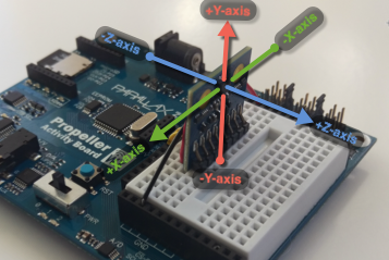
IMU initialize

The IMU initialize block sets up the communication between the Propeller chip and the compass module.
If you have defined a constant using the constant define block, the constant will show up in all of the pin menus and can be selected instead of a numbered pin:
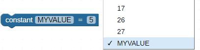
If you forget to use this block, a triangle warning icon will appear on other IMU blocks as a reminder: 
Set each drop-down to match the Propeller I/O pins connected to the IMU’s SCL, SDIO, CS_AG, and CS_M pins. It is not necessary to connect the INT_A/G or INT_M pins. However, they may be read using a check PIN block if they are connected. I/O pins available will vary by board type.
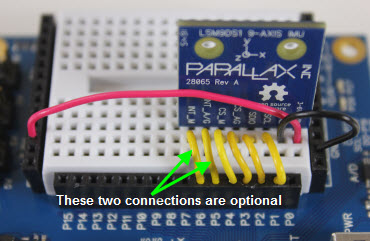
IMU calibrate magnetometer

The IMU calibrate magnetometer block is used to calibrate the magnetometer on the IMU module.
Use this block immediately after the IMU initialize block. Hold the IMU (or your project that includes the IMU) flat but in a space with enough room to rotate it around. Once the calibration has started, if you are using the ActivityBoard or FLiP, the P26 and P27 LEDs will turn on.
Once the calibration has started, it will collect samples for 30 seconds.
If you only plan to use the IMU as a compass (for heading using 2 of the axes), you will want to set your device flat and rotate it slowly around during the 30-second sample collection. If you need all 3 axes calibrated, you will need to slowly rotate your project around each of the IMU’s 3 axes during the 30 seconds sample collection.
You do not need to repeat the calibration again unless your environment (such as moving your project into or out of a building) or your location changes.
IMU read

The IMU read block stores the current accelerometer, gyroscope, or magnetometer measurements from each of the 3 axes into the specified variables. The Accelerometer measurements are in g-100ths. This means that a measurement of 1 g (1 Earth gravity) of acceleration will read as +100 in one direction or -100 in the opposite direction. Gyroscope measurements are in hundredths of degrees of rotation per second (DPS-100ths). Magnetometer measurements are in gauss-100ths.
IMU tilt

The IMU tilt block stores the current tilt angles measured by the IMU’s accelerometer, measured in degrees as an integer, ranging from -180 to 180. You must specify the axis that is pointing up/down (vertically) to ensure that your measurements are correct. The tilt of the remaining to axes are then stored in the variables specified by their respective drop-down menus.
IMU heading

The IMU heading block stores the current unadjusted heading measured by the IMU’s magnetometer, in degrees as an integer, ranging from 0 to 359. You must specify which axes are pointed in which directions relative to the observer for the code to correctly resolve the compass heading.
Calibrate your IMU’s magnetometer before using the IMU heading block. You may also need to re-calibrate it if your environment or location changes from the last time it was calibrated.