Schematic Symbols
As you go through various Parallax microcontroller tutorials, you will see schematics describing the circuits to be built. Below is a list of common symbols you might see in these schematics. Photos of some common components are included, but note, the photos are NOT to scale!
Protect your eyes! Safety eyewear is recommended when building circuits. Some devices, particulary polarized ones like electrolytic and tantalum capacitors, may explode if put into a circuit backwards. Always disconnect power when building or modifying a circuit. Always double-check your wiring of polarized components before reconnecting power.
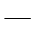
Wire
This symbol represents an electrical connection. A jumper wire can be used for this in a breadboard-based circuit.
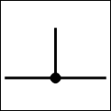
Wires (Connected)
This symbol represents a shared electrical connection between two components. When building a circuit, this electrical connection can be made by plugging a lead from each component into the same breadboard row.
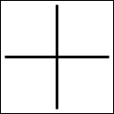
Wires (Not Connected)
This symbol represents wires that cross in a schematic for drawing convenience, but do not actually connect in a circuit. Don’t be fooled!
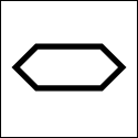
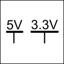
DC Supply Voltage
These symbols represent how much voltage to supply to your circuit; they may also show a value range or be labeled as Vcc, Vdd, or Vin.
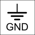
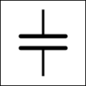
Ground
This symbol represents zero volts. It may be unlabeled, or labeled with GND (shown), Vss, or Vee.
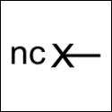
No Connection (nc)
This symbol represents a pin or lead (from a sensor or component) which is not electrically connected in the circuit. This symbol may be unlabeled, or labeled with nc (shown).
 Nothing to show here!
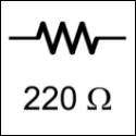
Resistor
A resistor limits electrical current. Resistance is in ohms, often denoted by the omega symbol. In a schematic, the resistance value is usually included near to the symbol (shown). Click here to learn about reading resistor color codes.
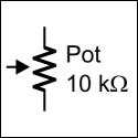
Potentiometer (Variable Resistor)
A potentiometer, also known as a variable resistor, has a resistance value determined by the position of an internal wiper (shown by the arrow). A label and/or upper maximum resistance value may be shown next to the symbol in a schematic, like the 10 kilo-ohm example below..
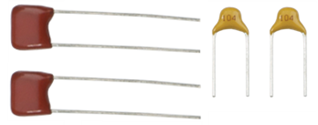
Capacitor, Non-polar (Monolithic)
Capacitors store electrical energy. Non-polar capacitors do not have positive and negative leads, so there is no “wrong way” to connect it in a circuit. Capacitors store electrical charge, like tiny batteries. The unit of measure is the farad. With microcontrollers, you will likely see these common sub-units:
- millifarads (mF) – thousandths of a farad
- microfarads (µF) – millionths of a farad
- nanofarads (nF) – billionths of a farad
- picofarads (pf) – trillionths of a farad
The 103 on the 0.01 µF capacitor is the number of picofarads: 10 + 3 zeros or 10,000, which is 1×10⁴.
CAUTION! Some capacitors that are made of tantalum look similar to non-polarized monolithic capapcitors. But tantalum capacitors are polarized! Tantalum capacitors that are put into a circuit in reverse may explode and release fragments at a high rate of speed. Use protective eyewear when building circuits with unfamiliar capacitors and other potentially polarized parts.)
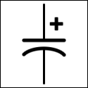
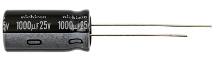
Capacitor, Polarized (Electrolytic)
Electrolytic capacitors store electrical energy but can only be connected in a circuit one way. The positive lead of a electrolytic capacitor is represented with a plus sign. You must use caution to correctly connect the positive and negative leads of polarized capacitors. Reversing the current by putting them in “backwards” can cause the capacitor to explode! See Capacitors above for an explanation of units.
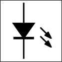
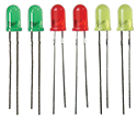
Light-Emitting Diode (LED)
LEDs convert electrical energy to light; they are commonly used to indicate the status of a circuit. The positive terminal (anode) is the flat spot of the triangle. LEDs come in many different packages, such individual LEDs and modules that include several in one package.

Transistor
Transistors control current flow.
![]()
![]()
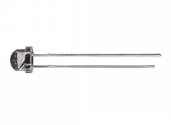
Phototransistor
Phototransistors restrict or allow current to flow proportional to the amount of light detected.
![]()
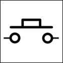
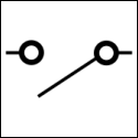
Push-buttons & Contact Switches
Normally open contact switches allow current to flow through a circuit only while being physically engaged. In the case of pushbuttons (left image), the button must be pressed or held down to allow current flow. In the case of whisker circuits (right image), the whisker must be touched or held against posts or headers to allow current flow. This type of switch is called “normally open” because its default state is not-pressed, or open.
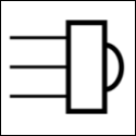
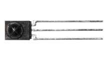
Infrared Receiver
Infrared receivers detect light emitted by infrared LEDs. These devices are often used together in a circuit for obstacle detection and/or avoidance. These devices have three connections: power, ground, and signal.
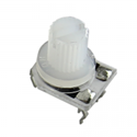
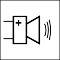
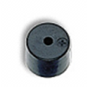
Piezospeaker
A piezospeaker creates sound when voltage is applied across its terminals. In the schematic symbol, the positive lead is represented by the plus sign. Take note of the positive lead marked by the plus sign on the speaker’s case.
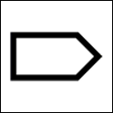
Microcontroller Output Pin
This symbol represents a microcontroller’s I/O pin functioning as an output, that is, sending a signal through a circuit to another device. The pointed end of this symbol faces away from the I/O pin label, such as P0, P1, P2, et cetera.
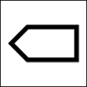
Microcontroller Input Pin
This symbol represents a microcontroller’s I/O pin functioning as an input, that is, receiving a signal through a circuit from another device. The pointed end of this symbol faces towards the I/O pin label, such as P0, P1, P2, et cetera.
Microcontroller Bi-directional Pin
This symbol represents a microcontroller’s I/O pin functioning as both and input and output in a circuit. It will be sending signals to, and receiving signals from, another device while the application’s program is running. One end of this symbol points towards the I/O pin label, such as P0, P1, P2, et cetera, the other end points away.