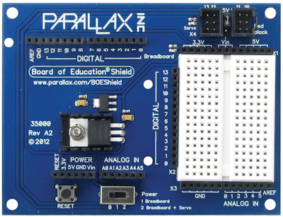
One of the best ways to experiment with an Arduino Uno microcontroller is pairing it with a Parallax Board Of Education (BOE) Shield. This product combines an Arduino shield, mini solderless breadboard, expanded I/O headers, and extra onboard 5V and 3.3V regulators.

While the BOE Shield was originally devised to be used on the Parallax Board of Education robot chassis, it’s also a great tool for small Arduino projects. Use it to test your Arduino KickStart tutorials in one compact space.
Because the solderless breadboard is integrated into the shield, most of your projects may be completed using only short jumper wires, such as the 100mm Male-Male Jumper Wires - 20 Pack.
Refer to the online BOE Shield Tutorials for step-by-step instructions for attaching your Arduino Uno to a BOE Shield. Once assembled, you can use the BOE shield as a convenient test bench for any KickStart example.
Providing Electrical Power
The BOE Shield derives its power from the Arduino board that's attached to it.
- Power just the Arduino by connecting it to your PC via a USB cable, or by connecting a battery pack or power adapter to the Arduino’s power plug (7-12 volts). Leave the 3-position power switch on the BOE Shield in the 0 (off) position.
- Power the Arduino and BOE Shield by plugging in a battery pack or power adapter to the Arduino (7-12 volts). Move the 3-position power switch to the 1 or 2 position.
Using the 3-Position Power Switch
The BOE Shield uses a 3-position switch to control the distribution of power to the connector pins surrounding the solderless breadboard:
| Position | What it Does |
| 0 | Disables power to the power pins along the top of the breadboard. The power pins near the middle of the shield remain active regardless of the position of the switch, and may be used whether the Arduino is powered by USB cable, or separate power supply. |
| 1 | Applies power to the power pins beside the breadboard, but not to the four servo headers. |
| 2 | Applies power to all breadboard pins, and the servo headers. |
Use the servo headers for fast and easy testing of the Parallax continuous or standard servo motors. Refer to the BOE Shield documentation for additional information and connecting and using servos with the shield.
Adapting the Breadboard Wiring Diagrams
The BOE Shield uses a somewhat different layout for the Arduino’s digital and analog I/O pin headers. All the digital pins are provided in a single row to the left of the solderless breadboard, as well as a duplicate set at the top of the BOE Shield.
The six analog pins, labeled A0 to A5, are likewise provided in two locations: along the bottom of the breadboard, and also near the center.
You may connect your projects to either set of pins, though for convenience, you'll likely want to use only the headers nearest the breadboard.
- Follow the hookup Arduino Uno diagram presented in the KickStart, plugging the jumper wire into the corresponding I/O pin on the BOE Shield.
- Use any available 5V and GND (ground) header pins to connect to power.
- Connect to the power pins beside the breadboard if you wish to control the power distribution through the 3-position switch.
If you use the power pins along the top and bottom of the breadboard, be sure to set the power switch to Position 1 or Position 2.
- Copyright: Creative Commons 3.0 SA license
