Build the Whisker Circuits
The directions below will guide you through building whisker switch circuits on your cyber:bot. The whisker switch wires connect to posts on the front corners of the robot.
- Put the cyber:bot board’s power switch in position 0.
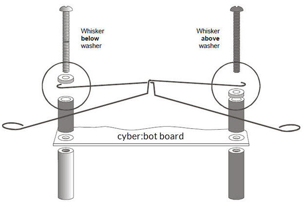
- Check to make sure the posts are already installed on your robot. If they are not, install them now using the parts list and picture below.
- (2) 7/8″ pan head 4-40 Phillips screws
- (2) ½″ round spacer
- (2) Nylon washers, size #4
- Loosen the post screws slightly and slip the hooked end of a whisker wire around each one. The whisker must go below the washer on one side, and above the washer on the other side.
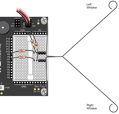
- Use the following parts to build the rest of the switch circuitry on the breadboard as shown below.
- (2) 3-pin m/m headers
- (2) resistors, 220 Ω (red-red-brown)
- (2) resistors, 10 kΩ (brown-black-orange)
- (misc) jumper wires
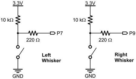
- Double-check your connections:
- 220 Ω resistors (red‑red-brown) connect digital pins 7 and 9 to their corresponding 3-pin headers.
- 10 kΩ resistors (brown-black-orange) connect 3.3 V to each 3-pin header.
- Make sure to adjust each whisker so that it is close to, but not touching, the 3-pin header on the breadboard. A distance of about 1/8″ (3 mm) is about right.