

The 96 x 64 Color OLED Display Module (#28087) [1] is easy to add to your BlocklyProp projects. It can be used for displaying graphics, text, and images in color. The display portion of the Color OLED module measures 0.95" diagonal, and contains 96 x 64 pixels. Each pixel can display 65536 different colors.

This tutorial shows you how to connect the 96 x 64 Color OLED Display Module to your Propeller Activity Board. Then, it will guide you through writing BlocklyProp programs to display text, numbers, and images on your OLED display. It covers using different fonts, different shapes, and different colors. It even demonstrates simple animation by moving a shape across the display.
*Any other Propeller development board with a similar 5 MHz oscillator and 64 KB EEPROM will likely work with this tutorial
Once you have completed this tutorial, you will be ready to use the 96 x 64 Color OLED Display Module with other sensors and accessories in your BlocklyProp projects.
The Color OLED module needs 7 connections to do its job. GND on the module must be connected to GND on the Activity Board, VCC should be connected to 3.3V, and every other pin (except the one marked N/C - which is an abbreviation for “no connection”), must be connected to an I/O pin.
The OLED initialize block is used to set up the Color OLED display module. The DIN, CLK, CS, D/C, and RES pins on the module must be matched to the Propeller Activity Board pins they are connected to:

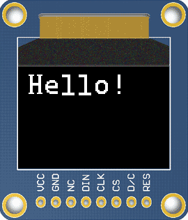
The test project is the classic "Hello World!" text often used to prove that a communication program is working.

The Color OLED will display the information sent to it by the Propeller:

The OLED initialize block sets up the connections between numbered Propeller I/O used to connect to each specific signal lines on the OLED display. The OLED print text block passes the characters in its text string block to the display for rendering.
CAUTION: Don’t leave the Color OLED on for long periods of time. OLEDs can burn out if they are left on and displaying the same image for more than an hour at a time. Use the OLED command block to “sleep” and “wake” your screen.
It is possible to use more than one OLED at a time in a project. The Tiny Tutorial video below uses two displays at once. Something to keep in mind for future projects after going through this tutorial!
When the OLED initialize block is used, it sets up the Propeller microcontroller to communicate with the Color OLED module. The OLED initialize block installs 1 small font, which allows you to print text and numbers to the OLED module’s screen. You may want to use a medium or large sized font instead. In order to use different fonts, you will have to install them into the EEPROM memory on your Activity Board.
The EEPROM memory on the Activity Board and Propeller FLiP can hold up to 64 kilobytes (KB) of data. The first 32 KB is used to hold your programs when you click “Save to EEPROM”. The remaining memory — often called upper EEPROM — is used to hold information that can be accessed by the programs you write.
The chart below illustrates how the EEPROM is used. When you install the Display Fonts, they use about 23 KB of EEPROM memory:
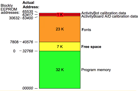
If you look carefully at the chart above, when Fonts are installed, there are about 7.8 kilobytes available for other uses. In BlocklyProp, that area is accessible via the Memory > EEPROM blocks.
Installing the fonts does not actually require any circuits, not even the OLED itself. The program to install the fonts is only a single block.

Four Fonts, Three Sizes — The default Sans font style does not need the OLED font loader block. But once you have loaded the OLED font loader block project to EEPROM, you have the fancy Serif, Script, and Bubble fonts to use. Here are the sizes available to each font:
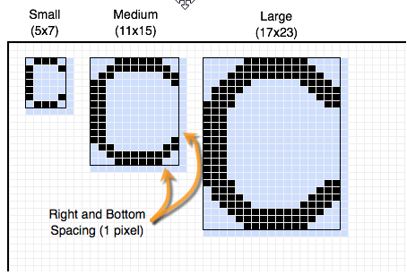
Fixed-width & fixed-height Fonts — This means that each character takes up the same amount of space. This makes it much easier to predict where characters will appear on your screen.
The width of each character increases by 6 pixels from small (6 pixels wide) to medium (12 pixels wide) to large (18 pixels wide). The height increases by 8 pixels from small (8 pixels tall) to medium (16 pixels tall) to large (24 pixels tall). Because there is a 1 pixel spacer on the right and top of each character, the actual character size is 1 pixel less:
Now that you have loaded fonts to your Propeller board’s EEPROM, you are ready to experiment with those different fonts and sizes. By default, the OLED print text block will use the Sans font in size small. You can now change that with the OLED text size block.

By default, the OLED print text block will use white text on a black background. The OLED font color block adds another element of fun and functionality!
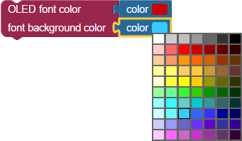
Add the OLED font color block to your project, just under the OLED set text block.
To use the Color OLED module, it is important to understand its coordinate system. Most computer graphics, displays, and terminals follow a similar convention - the top-left corner is the origin.
Look carefully at the graphic below. The display in the graphic shows a single white pixel in each corner of the screen. The grey text closest to each pixel represents that pixel’s coordinates. The top-left pixel is in row zero and column zero. You could also say that it’s x/y position is (0,0). Since the display is 96 pixels wide, and the first pixel is zero, the rightmost pixel is in column 95.
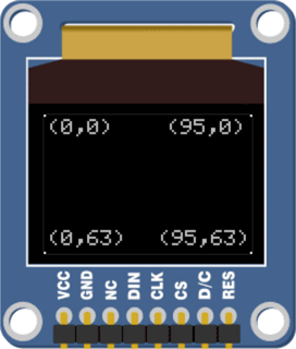
When we refer to the coordinates of a pixel, we use the notation (x,y), where x is how far across from left to right, and y is how far down from top to bottom.
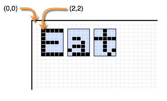
The cursor is the point where the Color OLED module begins printing text or numbers. If you set the cursor to (0,0), it will print text beginning at the top-left corner. If you set the cursor to (2,2), it will begin printing text 2 pixels left and 2 pixels down from the top-left corner:
This test program prints the Hello World message three times, using different starting coordinates each time.
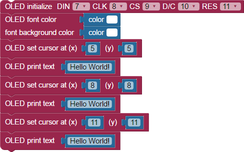
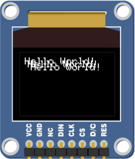
The program printed Hello World! three times, starting at different coordinates. Since the second and third prints' coordinates were close to the first, the three printings are overlapping. The background, or highlight color, of the text is transparent - you can see though it.
What color is transparent? — It depends!
If you want your text to cover up what’s underneath it, but you don’t want it to appear highlighted, set the background to match the background of the rest of the screen.
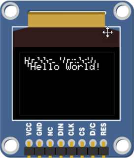
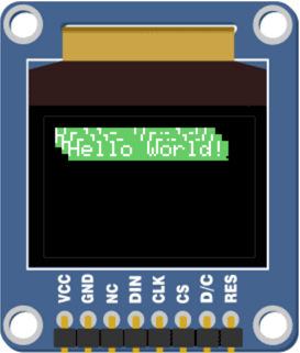
To boldly highlight text, set the font and the font background to different colors from the screen.
The screen will display:
The Color OLED module is a great way to display the data received from a sensor, such as the PING))) Ultrasonic Distance Sensor, or sensor or the Memsic Dual-Axis Accelerometer.
You can use the OLED print number block to send a number value to the Color OLED. This block can hold a number value, or a variable, or any expression that resolves as a number. It can display values as decimal, hexadecimal, or binary numbers.

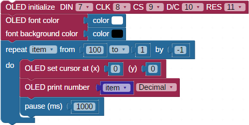
The example project uses a repeat item loop to display a value as it counts down from 100 to 1, updating the display once per second.
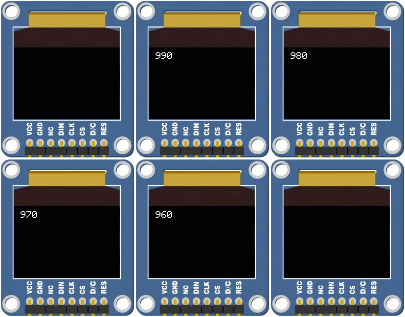
Your display should behave like the animated .gif below, which shows the first few iterations of the repeat item loop. You may notice that right away that something doesn’t look right!
After initializing the display, the OLED font color block sets the font to white, and the font background to black. This will let each number overwrite the previous number instead of overlapping them.
Next, the loop repeat item from 100 to 0 by 1 sets up our countdown. It starts off by setting the cursor to position 0,0 each time through the loop so each number will display in the upper left corner. The OLED print number block prints the current value of item each time through the loop. The pause 1000 block slows down the loop so it updates the display once per second.
So what is going wrong? The first time through the loop, item equals 100, and so the program prints “100” to the screen. Then, on the next trip through the loop when item is reduced by one and it prints “99” to the screen, the last “0” in the original “100” doesn’t get written over. So instead of 99, we see 990, then 980, and so forth. Eventually it counts down to display 100 again!
Numbers are text too - From the program above, you can see that the OLED font color block works with the OLED print number block, just the same way it does with the OLED print text block. Likewise, the OLED text size block works with the OLED print number block. So, as long the extra fonts are installed in uppper EEPROM, you can display your project's sensor values in large purple balloon numbers if that's what you want!
Now, let's fix the problem in the test code that seems to count down from 100 to 990 to 100 again! How do you fix this? Print a few spaces after the number each time you update it. In fact, a good practice to follow is add enough spaces for your smallest possible number to cover up your largest possible number.
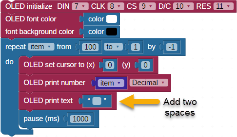
Here is a challenge that combines what you have learned so far.
The Color OLED module displays shapes as well as text and numbers. This means that you can create images on the OLED’s screen, and you can use those images for anything you can imagine: art, graphics, icons, math functions, user interfaces - the only limit is your imagination!
The easiest thing to draw is a single pixel! The following program will draw 100 random pixels.
![]()
![]()
The random number blocks provide a random value between 0 and the maximum screen dimension, given by the OLED max height and OLED max width blocks. These numbers are then used to set the position of the pixel drawn by the OLED draw pixel block. This then repeats 100 times, drawing 100 different pixels on the Color OLED’s screen. The pause 20 block slows down the process just enough so you can see the pixels appear individually instead of all at once.
To draw a line, you need to define a start and an end point - the OLED draw line block takes two x/y coordinates:
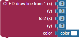
The following program will draw 10 different lines.


Experiment with the program above by drawing lines of different lengths and colors.
Taking Shape — In addition to pixels and lines, there are blocks that draw circles and triangles. Each shape has both a color and a fill setting that can be changed, but the shapes themselves are defined differently:
Out of Bounds — Lines and shapes can start “out of frame” where start or end points are outside of the screen’s view. For example, you could draw a line from (-5,-5) to (150,200) - both points are off-screen.
Let's try a program that will draw a rectangle and demonstrate its corner option. Every second, it will clear the screen and redraw the rectangle with increasing corner roundness.
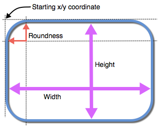


Notice that initially, the rectangle had no roundness at all (square corners). By the end of the program, the corners were very rounded.
Microcontrollers are built using lots and lots of transistors - and transistors are like switches. Switches can either be off or on. This means that microcontrollers only understand numbers when they can be written as a series of 1’s and 0’s. This is called binary. The Propeller microcontroller stores numbers as a series of 32 1’s and 0’s. For example, the number 238,472,910 in binary is:
0001110001101101100111011001110
The nice thing about binary numbers is that we can use them to store a few pieces of information in a single number. In BlocklyProp, color is stored into 24 of the 32 bits. 8 of the bits represent how much red there is, 8 of the bits represent how much green there is, and 8 of the bits represent how much blue there is in a color:

Each 8-bit part of the 32-bit number can hold a value ranging from 0 to 255.
You may have noticed a few blocks in the VALUES menu that refer to color:
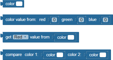
You will use some of these blocks to generate different colors for the shapes you will draw on your Color OLED’s screen.
This program will use the terminal to ask you for an amount of Red, Green, and Blue and use that information to draw a colored rectangle on the Color OLED’s screen. You will then be able to use this program to experiment with color and learn how the primary colors (Red, Green, and Blue) colors can be mixed together to create all of the other visible colors.
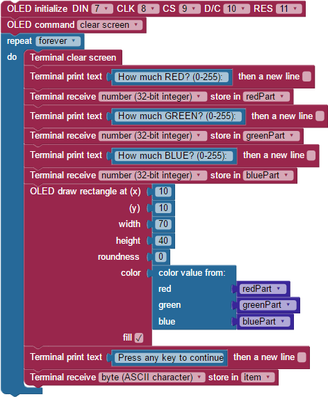
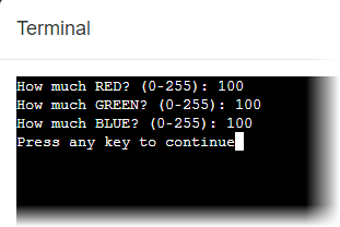
The Terminal window will appear and ask you to enter three values (one for red, one for green, and one for blue) between 0 and 255.
The program will combine the individual amounts of red, green, and blue into a color value and send it to the Color OLED screen:
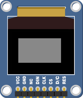
You may notice that your screen doesn’t represent the color exactly correctly - the Color OLED module uses very small Red, Green, and Blue LEDs inside each pixel to create a color, and the brightness of the component colors can vary slightly from module to module. This means that one module might have a slightly reddish tone while another module could have a slightly blueish tone.
Color Models — This display is using the RGB color model, where red, green, and blue light are mixed to produce many other colors. It is an excellent model for electronic displays that emit light, and its array of three values in the 0-255 range is an easy format to understand. However, in programming there are other formats for representing color, including Hex and CYMK. To learn more about the other systems, and to easily convert from RGB to other formats, see https://www.w3schools.com/colors/colors_converter.asp [5].
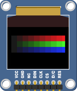
The next program will use the repeat item block to set the color (and position) of a rectangle.
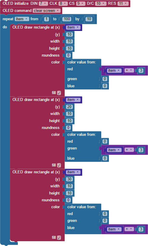
The Color OLED should display:
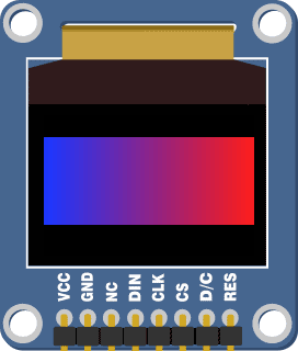
Instead of drawing a rectangle, try drawing lines to create a gradient - an area that transitions from one color to another:
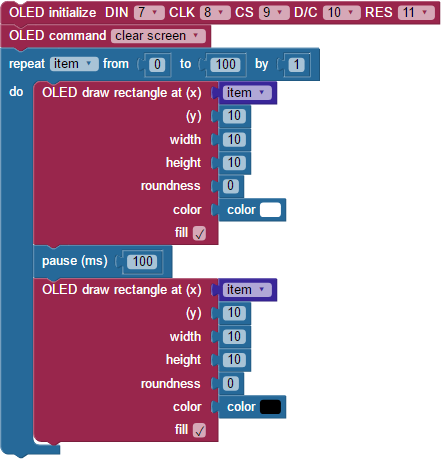
Animation means “lively” - and when we can make a shape on the screen move, it makes it appear alive. You can animate a shape or drawing by drawing it, erasing it, and redrawing it in a new position - if you do this enough times quickly enough, you create the appearance of movement.
Your screen should show a white box slowly moving from left to right across the Color OLED’s screen:
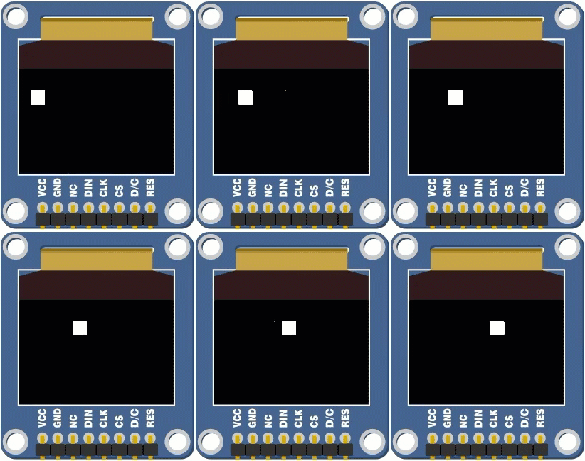
This example program draws a white rectangle, waits 1/10th of a second, draws a black rectangle to erase it, and draws a new white rectangle 1 pixel to the right of the original, and then repeats the process. This process makes the white rectangle appear to move across the screen.
How fast can you see? — It takes your eyes about 1/15th of a second to make out an image - this means that if the image changes slightly every 1/15th of a second, the images will blend together and appear to our brains as if the image is moving. Movies and TV show your eyes a new still image 25 to 30 times each second. Some computer screens refresh their screens up to 120 times each second. This refresh rate may be called the frame rate, labeled fps for frames per second.
There are two techniques that can be used to make a computerized animation seem even more realistic: begin your animation "off screen" and only "erase" what you have to. Let's try the first technique.
Did you notice that the full rectangle started at left edge, but disappeared into the right edge of the screen? To start it off-screen from the right edge, just start the repeat item value with a negative number small enough to "hide" the pixel width of the shape. It's a 10 x 10 square, so we'll use -10.

Now, the first rectangle is "drawn" completely off-screen. When the animation begins, it will move one to the screen one pixel-column at a time, giving a more naturally appearing motion.
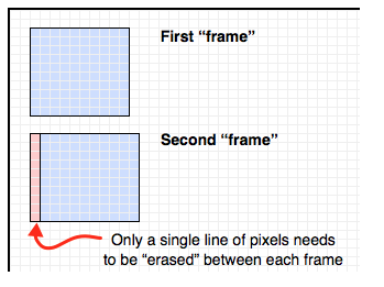
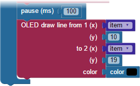
You may have noticed that in each loop, the entire rectangle is erased and redrawn. Instead of erasing the whole rectangle each time, you may only have to erase a small part of it - this results in a smoother looking animation:
So far, this tutorial has shown how to print text and draw shapes directly on the OLED display with a series of blocks. You can also display bitmap images stored on an SD card. This is easy if you are using the Propeller Activity Board WX, which has a microSD card slot built in.
First, you will need a tiny bitmap image! Such images could start as a photograph you take, or as digital artwork you create in other software. The example below started out as a 3.5 x 5 foot (about 1 x 1.5 meter) acrylic painting that was photographed and then reduced. Here are some tips:

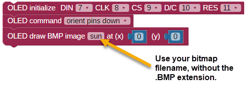
Keep in mind that the OLED is slow to update and will take approximately 20 seconds to fully display an image.
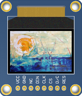
What is the outcome on the screen?
Now what is the outcome on the screen?
If you want to enhance your OLED projects with audio, there are a few things to take into account. The OLED draw image block and the WAV play block both access files stored on your Activity Board’s SD card. The OLED draw image block lets go of the SD card after fetching the .BMP file, but the WAV play block keeps ahold of the SD card for itself until your file is done playing or you release it with a WAV stop block.
You will need a .WAV file for this next example project. See our Sound Library [7] to download a properly-formatted WAV file. Or, follow the directions there to create or reformat your own. This example project uses bird.wav.
bird.wav [8]
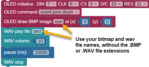
You should see the image fill the OLED display, then hear the WAV file playing.
Links
[1] http://www.parallax.com/product/28087
[2] http://www.parallax.com/product/32912
[3] https://learn.parallax.com/tutorials/language/blocklyprop/getting-started-blocklyprop-solo
[4] http://learn.parallax.com/tutorials/language/blocklyprop/simple-blocklyprop-programs-abwx
[5] https://www.w3schools.com/colors/colors_converter.asp
[6] https://www.parallax.com/product/8-gb-microsdhc-card/
[7] https://learn.parallax.com/support/reference/sound-library
[8] https://learn.parallax.com/sites/default/files/content/Reference/SoundLib/bird.wav
[9] https://www.parallax.com/product/900-00018