What is RF?
What is RF?
Some of the most exciting BASIC Stamp applications can be accomplished with Radio Frequency (RF) transmitters and receivers. The best part is that RF communication is all around! Every time you listen to the radio, use a cell phone, or watch television, RF transceivers are at work. RF communication uses radio waves instead of wires for exchanging signals, which is where the name “wireless communication” comes from. RF modules use frequencies (measured in Hz) to distinguish different radio signals, so in order for RF modules to “talk”, they must be operating on the same frequency. This activity uses the 433 MHz Parallax RF Transceiver modules. The modules have a transmitter that sends signals using radio waves that oscillate at 433 MHz, and a receiver that is tuned to the 433 MHz frequency, so a pair can communicate with each other.
Inside Wired Serial Communication
Since RF modules replace the wires that devices would otherwise need to exchange information, let’s first take a look at how BASIC Stamp modules would exchange information if they were connected by wires. BASIC Stamp modules (and a myriad of other digital devices) exchange information using serial communication. For example, a BASIC Stamp sending the character “E” to another BASIC Stamp could use the command SEROUT TxPin, 16470, [“E”]. You can look up the SEROUT command in the BASIC Stamp Manual or the BASIC Stamp Editor’s Help feature. One of the thing’s you’ll find is a table that tells you when the SEROUT command’s baudmode argument is set to 16470, it means that 8-bit data is sent inverted at a baud rate of 2400 bits/second.
Figure 1 shows an example of this exchange. Since the baud rate is 2400 bits/second, each high/low signal has to last for 1/2400 of a second. Inverted means that every binary 1 is transmitted as a 0, and vice-versa, and 8-bit means that each message has a byte’s worth of information (8 bits).
Figure 1 – Serial Transmission Between Two Connected BASIC Stamp Modules
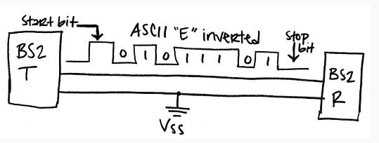
The ASCII value for the character “E” is 69, which is %01000101 in binary. So why does it appear that the data is transmitted as %101011101?
The answer is for two reasons. First, the SEROUT command is sending ‘inverted’ data, and second, serial communication always sends its values least significant bit (LSB) first.
- ‘Inverted’ changes all the 1 bits to 0, and all the 0 bits to 1. In the case of our ASCII value, it transforms %01000101 to %10111010.
- ‘LSB first’ sends the rightmost digit first, followed by the second digit from the right, and so on. That’s why the diagram shows all the digits backwards, as %01011101.
A serial message also has a start and stop bit, shown below in Figure 2. At a baud rate of 2400 bits-per-second (inverted), the start bit is a high signal that lasts 1/2400 of a second, and it signals that 8 more 1/2400 of a second bits are on their way. The stop bit is the minimum time before the transmitter is allowed to send another byte. The BASIC Stamp uses 1 stop bit, which at 2400 bits/second means that the transmitter has to wait at least 1/2400 of a second before sending the next byte.
Figure 2 – How Data is Transmitted Serially
![]()
Inside Wireless Serial Communication
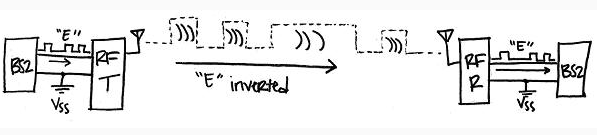
So we’ve covered transmitting serial data when two BASIC Stamp modules are connected. What if we want them to transmit the data wirelessly, like we will in the following activity? Does the theory change completely? Not at all. In fact, you can simply replace the wire with an RF transmitter and receiver, and the two BASIC Stamp modules can still exchange data as though they were using a wire. Figure 3 shows how this works. The only difference is that the transmitter gets data from the BASIC Stamp and sends it out through an antenna and into the air via radio waves, and the receiver module demodulates the radio signals back to wired serial signals and transmits them to the receiving BASIC Stamp.
Figure 3 – How Data is Transmitted Wirelessly
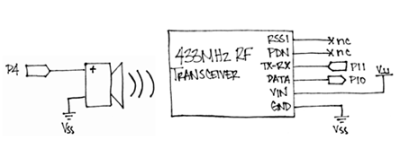
Schematics and Building the Circuits
- Build the two circuits as shown below, using one BASIC Stamp HomeWork Board (or Board of Education) per circuit.
Figure 4 – RF Transmitter Board Schematic
![]()
Figure 5 – RF Receiver Board Schematic