Skip to content
Parallax Learn

Parallax Learn

  • Welcome
  • Tutorials
        • Tutorial Series head tag

          Tutorial Series
        • Tutorial Series

          The special, classroom-ready series pages are organized collections of tutorials for our most popular hardware and/or languages. The tutorials for each topic are conveniently accessible from a single page, shown in the order it is recommended that they be completed.
        • Robotics Series Head tag

          Robotics Series
        • Robotics Series

          • Artificial Intelligence
          • Cybersecurity: Radio Data tutorialCybersecurity
          • cyber:bot + Python
          • cyber:bot + MakeCode
          • Boe-Bot Tutorial SeriesBoe-Bot
          • Arduino Shield-Bot
          • ActivityBot with C TutorialsActivityBot + C
          • ActivityBot with BlocklyProp Tutorial SeriesActivityBot + BlocklyProp
          • Scribbler 3 Tutorial SeriesScribbler 3
        • Electronics & Programming Series Head tag

          Electronics & Programming Series
          • BS2 Board of Education Tutorial SeriesBS2 Board of Education
          • Propeller C-Language BasicsPropeller C Basics
          • FLiP Try-It Kit C Tutorial SeriesFLiP Try-It Kit + C
          • FLiP Try-It Kit BlocklyProp TutorialsFLiP Try-It Kit + BlocklyProp
          • Badge WX Tutorial SeriesBadge WX
          • Propeller BlocklyProp Basics and ProjectsPropeller BlocklyProp Basics
          • View All Tutorial Series »
        • Browse Tutorials
        • Browse Tutorials

          Individual tutorials sorted by robot or kit, and language.
        • By Robot or Kit
          • ActivityBot
          • SumoBot WX
          • Boe-Bot
          • Shield-Bot
          • cyber:bot
          • Badge WX
          • ELEV-8
          • ARLO
        • By Language
        • By Language

          • Propeller C
          • Arduino
          • BlocklyProp
          • PBASIC
          • Python
          • MakeCode
          • View All Tutorials »
  • Educators
  • Reference
  • Downloads
  • Home
  • All Courses

Arlo Robot Assembly Guide

Curriculum

  • 1 Section
  • 47 Lessons
  • Lifetime
Expand all sectionsCollapse all sections
  • Arlo Robot Assembly Guide
    47
    • 1.1
      Section 0 – Getting Ready to Build Arlo
    • 1.2
      Section 1 – Motor Mount and Wheel Kit Assembly
    • 1.3
      Step 1 – Axle Assemblies
    • 1.4
      Step 2 – Motor to Bearing Block Assembly
    • 1.5
      Step 3 – Drive Axle Pin
    • 1.6
      Step 4 – Bearing Block and Axle
    • 1.7
      Step 5 – Soldering the Encoder Connectors
    • 1.8
      Step 6 – Encoder Cables
    • 1.9
      Step 7 – Encoder Assemblies
    • 1.10
      Step 8 – Drive Wheels
    • 1.11
      Step 9 – Wheel Assemblies to Drive Shaft
    • 1.12
      Section 2 – Caster Wheel Kits
    • 1.13
      Step 10 – Swivel Rod and Mounting Plate
    • 1.14
      Step 11 – Swivel Block
    • 1.15
      Step 12 – Flange Bearings
    • 1.16
      Step 13 – Shaft Collar and Swivel Post
    • 1.17
      Section 3 – Mounting Wheel Assemblies
    • 1.18
      Step 14 – Lay Out the Parts
    • 1.19
      Step 15 – Motor Mounts to Arlo Base
    • 1.20
      Step 16 – Casters to Arlo Base
    • 1.21
      Step 17 – Screws and Standoffs
    • 1.22
      Section 4 – Arlo Power Distribution Board
    • 1.23
      Step 18 – Low-Profile Components
    • 1.24
      Step 19 – Diodes
    • 1.25
      Step 20 – Fuse Holders
    • 1.26
      Step 21 – Terminal Blocks
    • 1.27
      Step 22 – Switch Terminals
    • 1.28
      Step 23 – Charging Power Jack
    • 1.29
      Step 24 – Voltage Regulators and Heat Sinks
    • 1.30
      Step 25 – Polarized Capacitors
    • 1.31
      Step 26 – Switch Plate
    • 1.32
      Step 27 – Switch Plate Assembly to PDB
    • 1.33
      Section 5 – Batteries and Battery Tray
    • 1.34
      Step 28 – Prepare Battery and Tray
    • 1.35
      Step 29 – Batteries and Tray
    • 1.36
      Section 6 – Assembling and Mounting the Ping))) Sensors
    • 1.37
      Step 30 – Light Pipe and Protector Stands
    • 1.38
      Step 31 – Attach Ping)))s to Stands
    • 1.39
      Section 7 – Control Components and DHB-10 Connections
    • 1.40
      Step 32 – Arlo Power Distribution Board
    • 1.41
      Step 33 – DHB-10 and Control Board
    • 1.42
      Section 8 – Arlo Top Deck
    • 1.43
      Step 34 – Wiring the DHB-10 Power Connections
    • 1.44
      Step 35 – Wire PDB to Battery
    • 1.45
      Step 36 – Prep the Barrel Jack Connection
    • 1.46
      Step 37 – Connecting Power & Encoders
    • 1.47
      Step 38 – Mount Top Deck

Step 28 – Prepare Battery and Tray

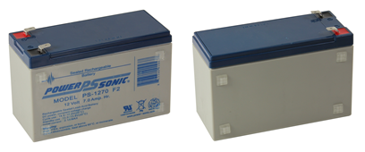
The battery tray can accommodate either one or two 12 V, 8 amp-hour sealed lead acid batteries depending on your power and load requirements. Batteries such as the PowerSonic #1270 or equivalent work well.

If you are building a two-battery system, follow these instructions and the ones at the beginning of Step 29. If you’re only going to build a one-battery system, then follow these instructions for your single battery and refer to the Single Battery Configuration instructions at the end of Step 29. The Arlo Full Kit includes both the one and two-battery system components.

  • Place (4) square rubber feet on both sides of each battery – that’s a total of (16) feet – 8 on each battery. 

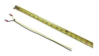
  • Cut 4″ off of the black wire and 4″ off of the yellow wire (to be used for DHB-10 connections, later on). Set aside.
  • Fold the remaining black wire in half and cut so you have two 13″ pieces.
  • Fold the remaining yellow wire in half and cut so you have two 13″ pieces.
  • Strip 1/4″ from both ends of the (2) black and (2) yellow wires.
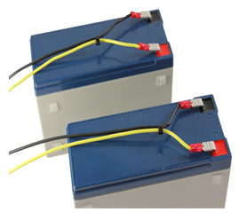
  • Crimp (or solder if you prefer) a ¼” female quick-connect to one end of the black wires and one end of the yellow wires as shown below. Using your wire crimper, firmly squeeze and crimp the terminal, causing it to bind to the bare wire. We also recommend that you solder the terminals to the wires (if possible) as this will be a stronger and more reliable connection.

  • Place a zip-tie about 1.5” from the end of the crimp terminals as shown above.
  • Tape over the uncrimped, stripped wire ends so that no wire is exposed.

Important! Make sure you tape over the uncrimped wire ends (as mentioned above) – this will help prevent any accidental shorting of the batteries until they’re ready for their final connections. Be absolutely sure you have fully covered the exposed wire. Once connected to the batteries it is very important you do not allow wire ends to touch each other!

  • Attach the wires to the batteries as shown. Be sure to observe the proper polarity: black is negative, connect it to the black battery terminal; the yellow wire should be connected to 12V positive.


Printer-friendly version
Section 5 – Batteries and Battery Tray
Prev
Step 29 – Batteries and Tray
Next

DISCUSSION FORUMS | PARALLAX INC. STORE

About | Terms of Use | Feedback: learn@parallax.com | Copyright©Parallax Inc. 2024

© 2026 Parallax Learn • Built with GeneratePress